
I posted about my problem on reddit yesterday and got a lot of very helpful suggestions. The top voted answer was that switching all those LEDs caused a current transient that shows up in my hall effect line. It probably doesn’t help that I have a long thing Vcc line to the hall effect sensor and that I have a long thin output line from the hall effect sensor running directly under the LEDs and a huge Vcc plane (which is only there due to my poor board design).
I proved this theory by first lifting Vcc from the LED driver, preventing it from pulling current, but keeping everything else the same. This eliminated the problem! Then I realized I didn’t really need to do that–I could have just as well initialized the LED driver to turn all the LEDs off. But finally I realized that probably switching 2 LEDs (turning 1 on and one off) wouldn’t draw too much current, so I soldered Vcc back on and gave that a try:
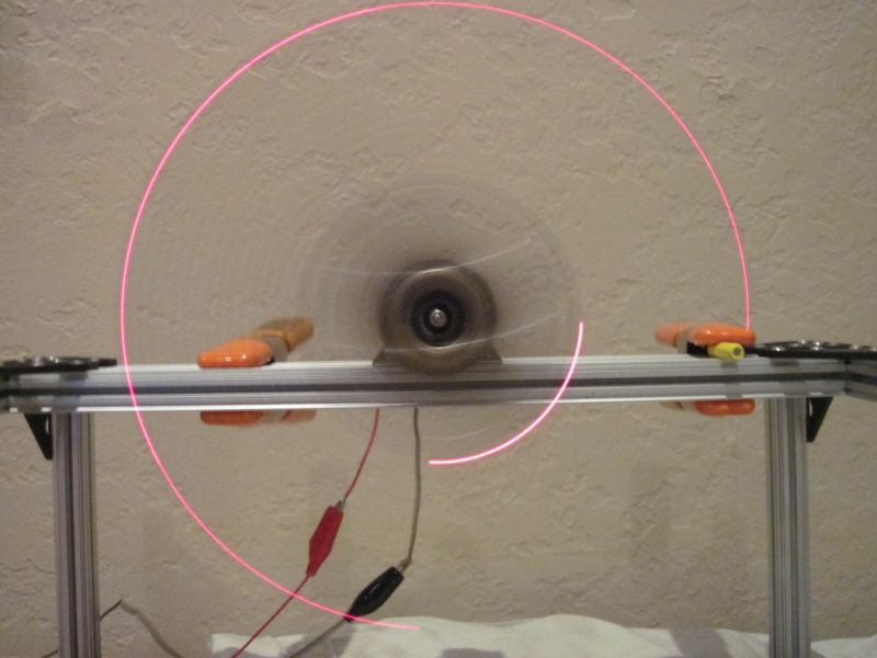
Hall effect sensor works exactly as expected now with no glitches!
Works perfectly, thus providing even more evidence that’s what the problem is.
Now I just need to find a way to get some more caps added on there…