Test bed enhancements

I haven’t done a lot with the spinner lately. My last test was to make a straight horizontal line that was not along the axis. I had problems with that which I attributed to not having enough high resolution timers, so I set it aside to play with my electromagnet tests. But, one thing that was still bugging me was having to use alligator clips to turn the motor on and off. That didn’t make a consistently good connection and the motor speed was clearly unstable at time. So, I finally hooked up my 69¢ switch:

SpinnerSwitchTest

If you look close, you can also see the horizontal line test. In fact, now that I look at it, the right hand side actually looks like I expect. It’s a pretty straight line. The left side is also straight, just not horizontal. Hmmm… I wonder if my real problem is just with my algorithm for calculating the line. There may be some hope here yet…

But the switch works much better than my old technique. The motor reliably turns on and off and runs at a constant speed now! So future tests will go much more smoothly.


Counter Test 2

Counter Test 2 works, but not quite right. For some reason, I have to set the prescaler on timer 2 to /64. At first, that worked quite well and gave me exactly what I expected, but by the time I got the camera out, the lines were no longer at 3, 6, 9, and 12:

Those lines should be at 3, 6, 9, 12 o'clock. Something's not quite right...

Those lines should be at 3, 6, 9, 12 o’clock. Something’s not quite right…

I suspect my problem here is that I should really be adjusting the prescalers on the fly instead of using the hardcoded values I designed in. My guess is that I’m overflowing what will fit into the 8 bit timer. I wish I could tell what I was writing in there. I may need to write the binary value again.

The code I used for this is:

1
2
3
4
5
6
7
8
9
10
11
12
13
14
15
16
17
18
19
20
21
22
23
24
25
26
27
28
29
30
31
32
33
34
35
36
37
38
39
40
41
42
43
44
45
46
47
48
49
50
51
52
53
54
55
56
57
58
59
60
61
62
63
64
65
66
67
68
69
70
71
72
73
74
75
76
77
78
79
80
81
82
83
84
85
86
87
88
89
90
91
92
93
94
95
96
97
98
99
// Using the spinner board to test 328 counters
 
#include <SPI.h>
 
const int HALL  =  2; // PD2
const int BLANK =  8; // PB0
const int LAT   =  9; // PB1
 
const int HALL_INT = 0; // Hall effect interrupt 0 on PD2 (INT0)
 
unsigned int savedCounter = 0;
unsigned int slice = 0;
 
void hallStart(void) {
  // TCNT1 is counts per full revolution
  savedCounter = TCNT1;
  TCNT1 = 0;
 
  // Also reset TCNt2 (slice counter) so we always start in a known
  // state
  TCNT2 = 0;
 
  // Calculate a new compare value for timer 2 based on how fast our last revolution was.
  // 512 angle slices, so divide the savedCounter by 512 to get the count per slice
  // But we also have a /8 prescaler, so instead divide by 4096
  int sliceCount = savedCounter / 4096;
 
  // Saved the new slice counter
  OCR2A = sliceCount;  
 
  // Reset the slice number
  slice = 0;
 
  // Now start the 8 bit counter 2
  TCCR2B = 6;                   // Set /256 prescaler
}
 
// ISR for the timer to switch the LEDs
ISR(TIMER2_COMPA_vect)
{
  if (slice == 0 || slice == 128 || slice == 256 || slice == 384)
  {
    setLeds(0xFFFF);
  }
  else if (slice == 1 || slice == 129 || slice == 257 || slice == 385)
  {
    setLeds(0x0001);
  }
 
  slice++;
}
 
void setup() {
  digitalWrite(LAT, LOW);
  pinMode(LAT, OUTPUT);     
 
  digitalWrite(BLANK, HIGH);
  pinMode(BLANK, OUTPUT);     
 
  pinMode(HALL, INPUT_PULLUP);
 
  // Setup the 16 bit counter counter 1
  TCCR1A = 0;                   // Turn off output compare modes
  TCCR1B = 2;                   // Turn on clk/8 prescaler
 
  // Setup 8 bit counter 2
  TCCR2A = 2;                   // CTC mode
  TCCR2B = 0;                   // Start with timer off
  TIMSK2 = 2;                   // Enable Output Compare A interrupt
 
  attachInterrupt(HALL_INT, hallStart, FALLING);
 
  SPI.begin();
  SPI.setDataMode(SPI_MODE0);
  SPI.setBitOrder(LSBFIRST);
  SPI.setClockDivider(SPI_CLOCK_DIV2); // Datasheet says 35 MHz max, so 8 MHz is fine
 
  TCNT1 = 0;
}
 
void setLeds(unsigned int pattern) {
  // Blank the LEDS
  digitalWrite(BLANK, HIGH);
 
  // Transfer the data
  SPI.transfer(pattern & 0xFF);
  SPI.transfer(pattern >> 8);
 
  // Latch the data
  digitalWrite(LAT, HIGH);
  digitalWrite(LAT, LOW);
 
  // Unblank the LEDS
  digitalWrite(BLANK, LOW);
}
 
void loop() {
  // That's right--nothing to do here
}


Counter Test 1

My first test actually went quite well. The counter worked just like I expected and I got the counter information I wanted:

LEDs displaying a binary pattern showing the value of the counter for how long the last rotation took. MSB is the innermost LED.

LEDs displaying a binary pattern showing the value of the counter for how long the last rotation took. MSB is the innermost LED.

For this picture, I used a flash, then kept the shutter open a bit. The spinner is actually traveling clockwise, so the trail of LEDs is actually in front of the spinner, not behind it as you would expect.

Anyway–the reason I used the flash was so I could see where each of the LEDs was mounted and could accurately count which ones are off. The MSB is the innermost one, so this counter value is 100011000100000b which is 4620h. This is about 2.5 times smaller than what I predicted. The counter values also change a lot more than I expected. I thought the least significant 2-3 bits would vary, but I actually see the least significant 8-9 bits changing. I know the battery is running low for my battery, so maybe the counter values I’m seeing are accurate.

Here’s the code I used to do this:

1
2
3
4
5
6
7
8
9
10
11
12
13
14
15
16
17
18
19
20
21
22
23
24
25
26
27
28
29
30
31
32
33
34
35
36
37
38
39
40
41
42
43
44
45
46
47
48
49
50
51
52
53
54
55
56
57
58
59
60
61
62
//  Using the spinner board to test 328 counters
 
#include <SPI.h>
 
const int HALL  =  2; // PD2
const int BLANK =  8; // PB0
const int LAT   =  9; // PB1
 
const int HALL_INT = 0; // Hall effect interrupt 0 on PD2 (INT0)
 
unsigned int savedCounter = 0;
 
void hallStart(void) {
  savedCounter = TCNT1;
  TCNT1 = 0;
}
 
void setup() {
  digitalWrite(LAT, LOW);
  pinMode(LAT, OUTPUT);     
 
  digitalWrite(BLANK, HIGH);
  pinMode(BLANK, OUTPUT);     
 
  pinMode(HALL, INPUT_PULLUP);
 
  // Setup the 16 bit counter
  TCCR1A = 0;                   // Turn off output compare modes
  TCCR1B = 2;                   // Turn on clk/8 input
 
  attachInterrupt(HALL_INT, hallStart, FALLING);
 
  SPI.begin();
  SPI.setDataMode(SPI_MODE0);
  SPI.setBitOrder(LSBFIRST);
  SPI.setClockDivider(SPI_CLOCK_DIV2); // Datasheet says 35 MHz max, so 8 MHz is fine
 
  TCNT1 = 0;
}
 
void setLeds(unsigned int pattern) {
  // Blank the LEDS
  digitalWrite(BLANK, HIGH);
 
  // Transfer the data
  SPI.transfer(pattern & 0xFF);
  SPI.transfer(pattern >> 8);
 
  // Latch the data
  digitalWrite(LAT, HIGH);
  digitalWrite(LAT, LOW);
 
  // Unblank the LEDS
  digitalWrite(BLANK, LOW);
}
 
void loop() {
  if (savedCounter != 0) {
    setLeds(savedCounter);
    savedCounter = 0;
  }
}

So, the only way to find out if my counter values are correct is to do the next test:

  • Each time I get the hall effect interrupt, read the 16 bit counter (counter 1)
  • Divide that by 4096, which is 512 (the number of slices) * 8 (the prescaler), then set that value in output compare A register for 8 bit timer 2. In CTC mode, this gives us an interrupt every time the counter value is matched.
  • Each time we get a timer 2 interrupt, increment the slice counter. On slices 0, 128, 256, and 384, turn on all the LEDs for one slice. This should display lines at the 12:00, 3:00, 6:00, and 9:00 positions


Polar vs. rectangular

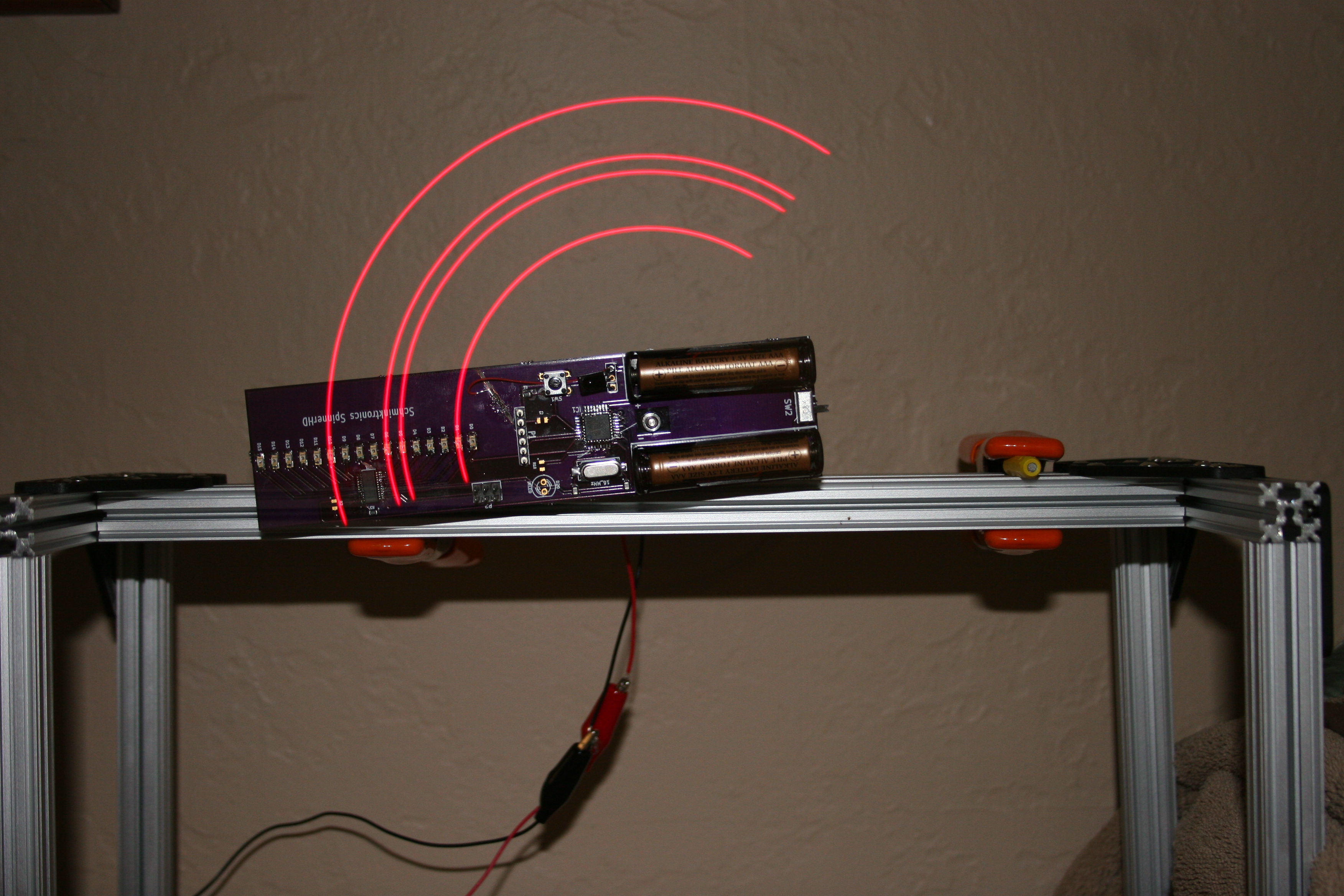
Now that the board is working, I thought I’d try a more interesting pattern, so I started with a sine wave. I wrote a quick python script to generate a nice looking sine wave:

1
2
3
4
5
6
7
8
9
10
11
12
13
14
15
16
17
18
19
20
import math
 
rows = 16
columns = 512
 
print "#define SIN_PATTERN_MAX %d" % columns
print "const int sinPattern[SIN_PATTERN_MAX] = {"
 
for x in range(0,columns):
    realx = 2 * math.pi * x / columns
    val =  (rows / 2) + (rows / 2)  * math.sin(realx)
    y = math.trunc ( val )
    if y &gt; (rows - 1):
        y = rows - 1
    #print '%*s' % ((y + 1), '*')
    print '0x%04X, ' % (1&lt;&lt;y),
    if (x &gt; 6 and (x - 7) % 8 == 0):
        print
 
print "};"

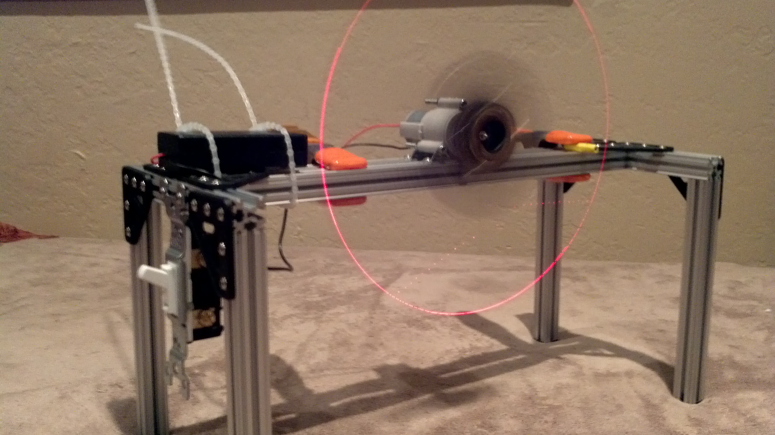
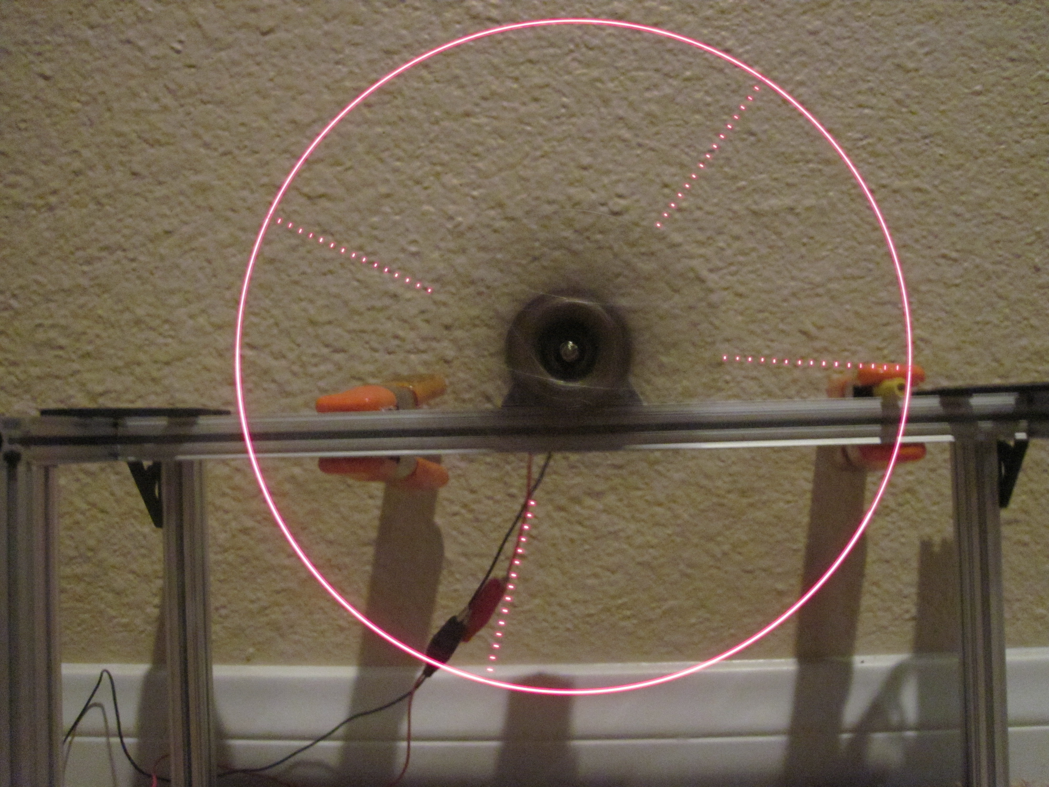
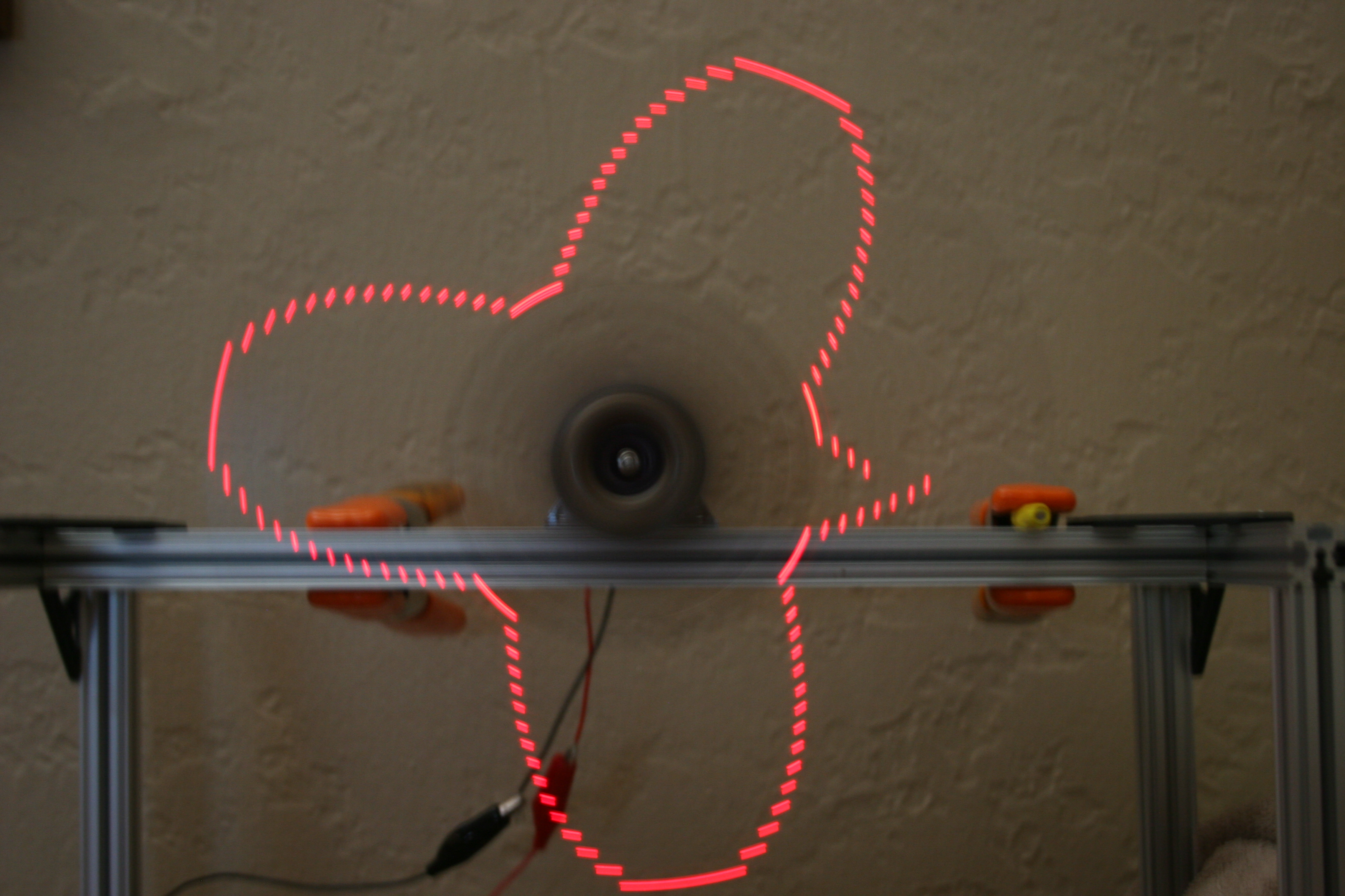
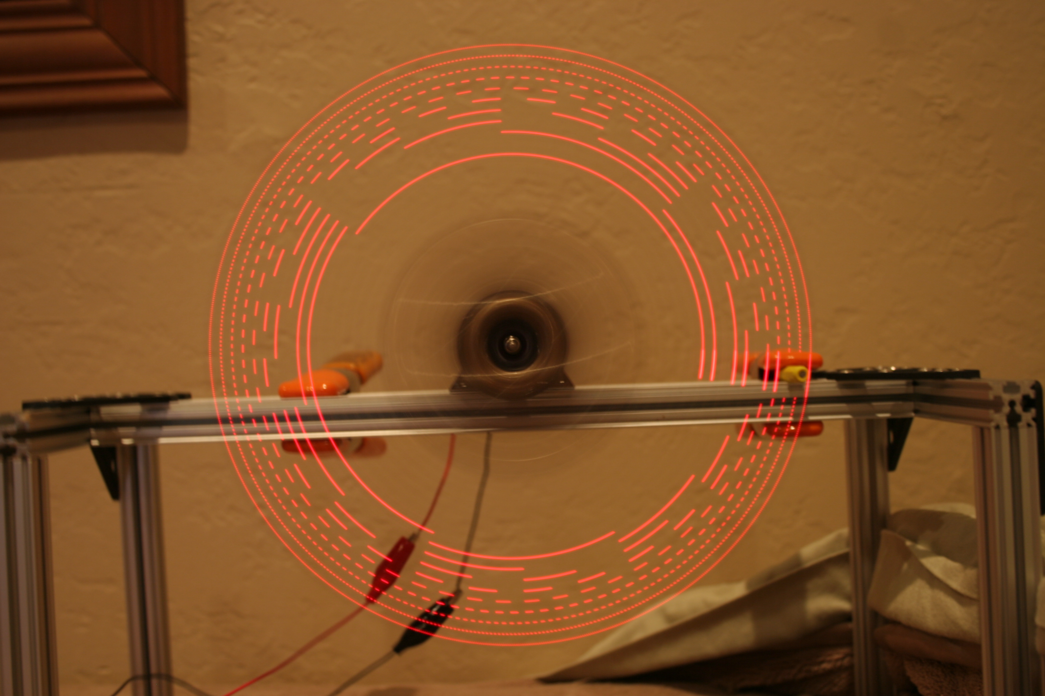
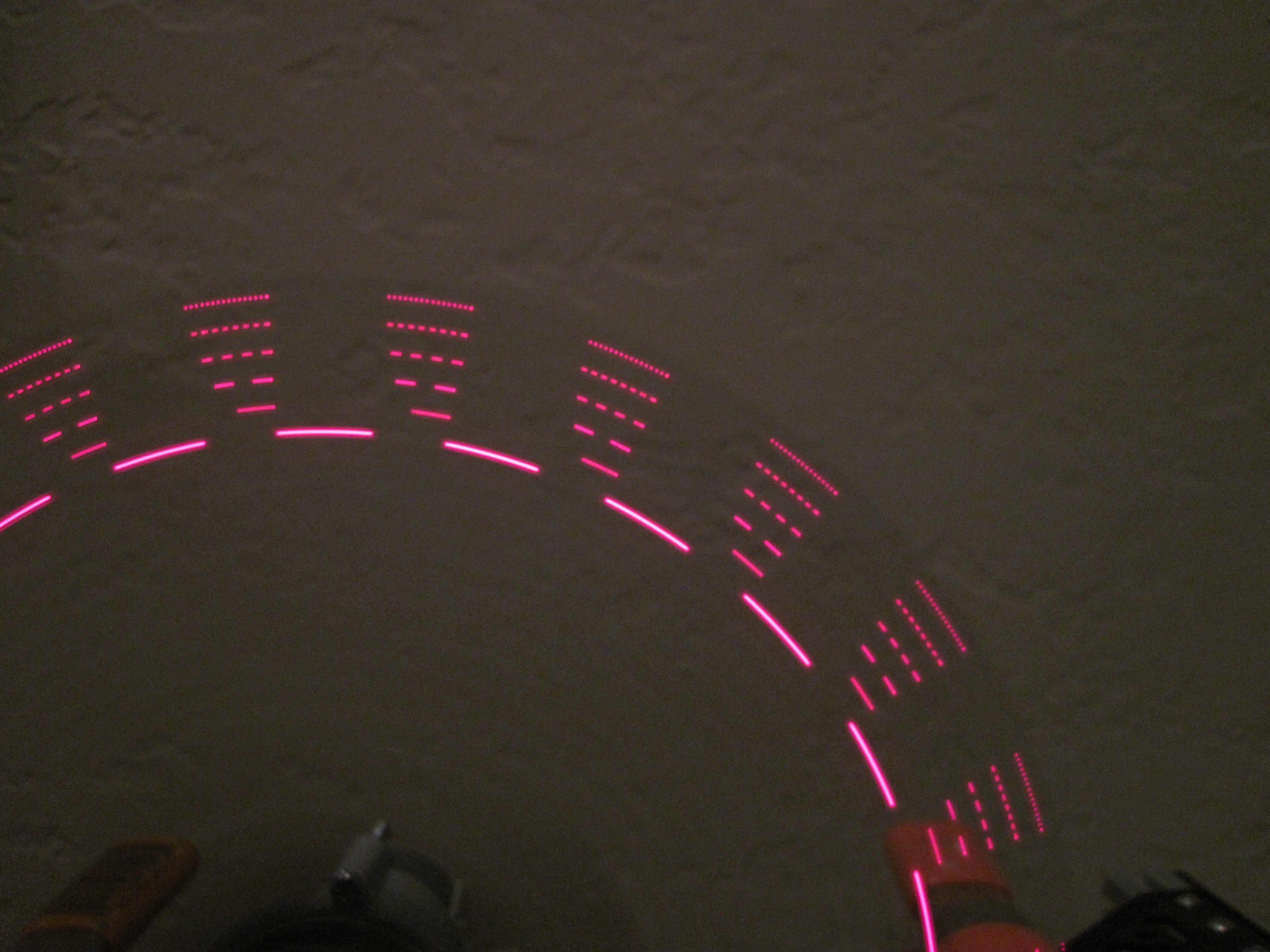
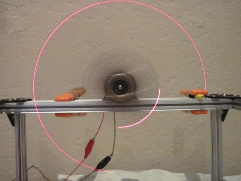
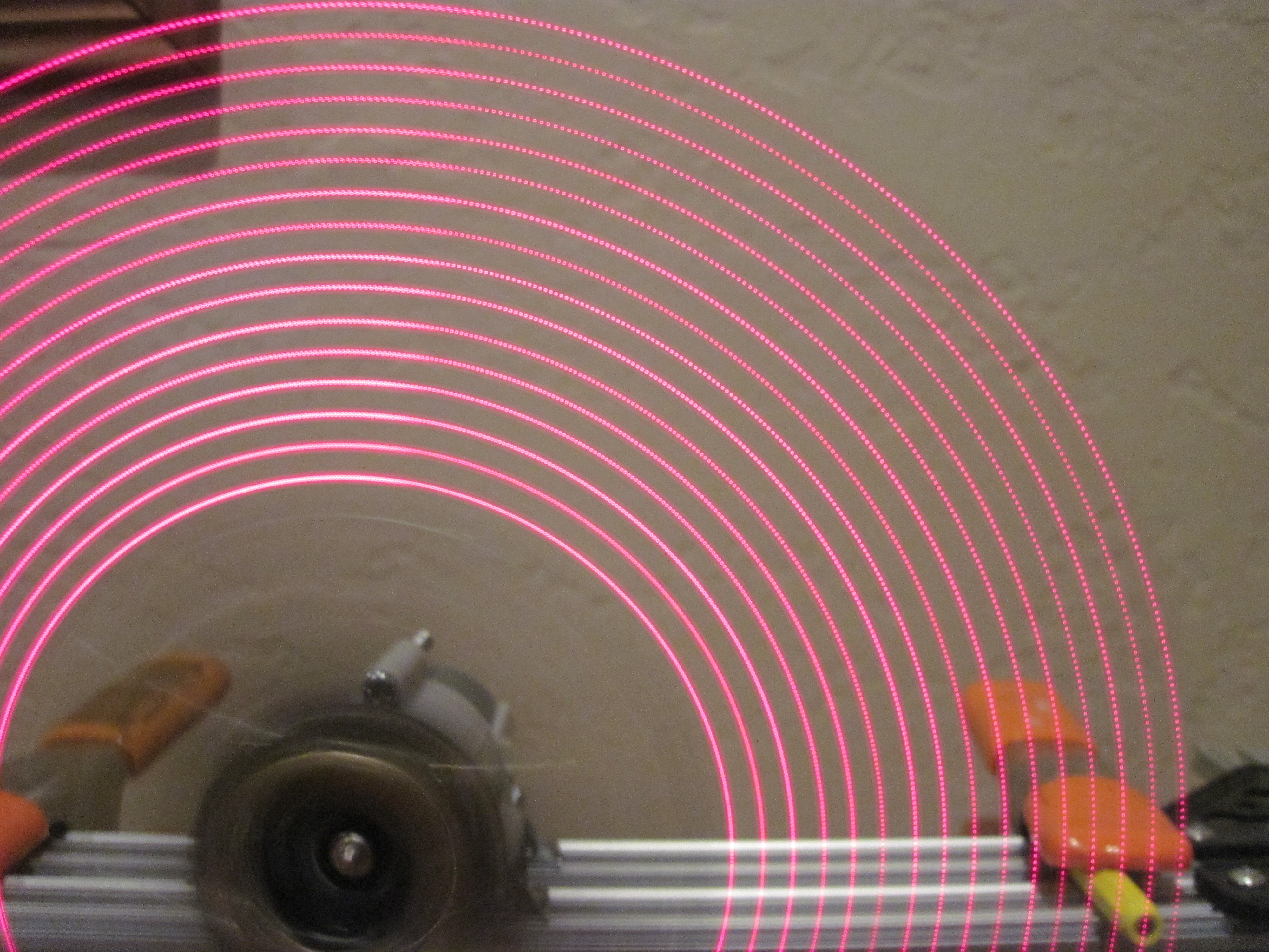
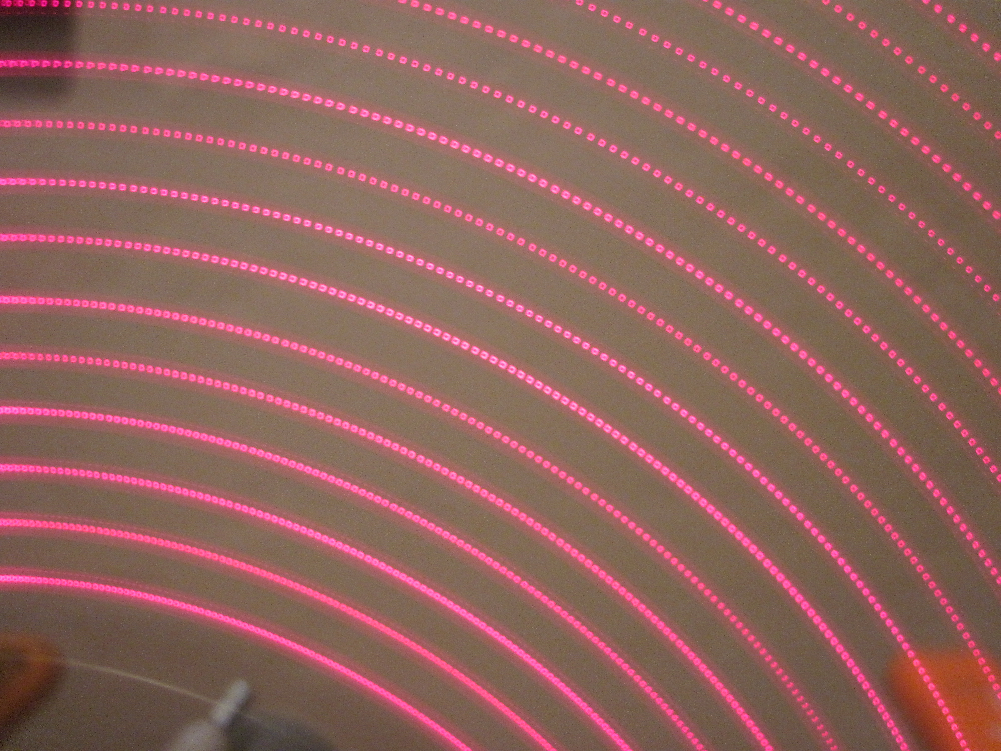
Looks great on the console (using that commented out line), but when I display it on the spinner, it looks terrible:

Sorry--I was lazy at trying to get the camera setup to take this entirely in focus and without extra motion.

Sorry–I was lazy at trying to get the camera setup to take this entirely in focus and without extra motion.

Obviously this doesn’t work well at all. I need to add correction for the different distances. I quickly realized that the spinner uses polar coordinates which the things I generally want to display use cartesian coordinates.Clearly what I need to do is convert between them!

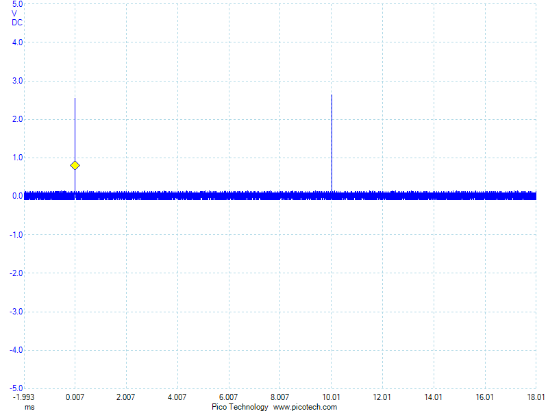
In order to do that, for each LED, I need to know the distance from the center and the current angle. The distances are fixed and angles can be calculated. I know when the spinner is at one specific angle (in line with the magnet) and I can use one of the counters to determine how long it takes to go around one rotation. Once I know that, I can split that time into equal parts and use that to calculate the current angle.

Will this plan work? According to the datasheet, my motor runs at 10,500 rpm. I’ve got that on a 4:1 gearing so it runs at (10,500 / 4) = 2625 rpm, which is (2625 / 60) = 43.75 rps.

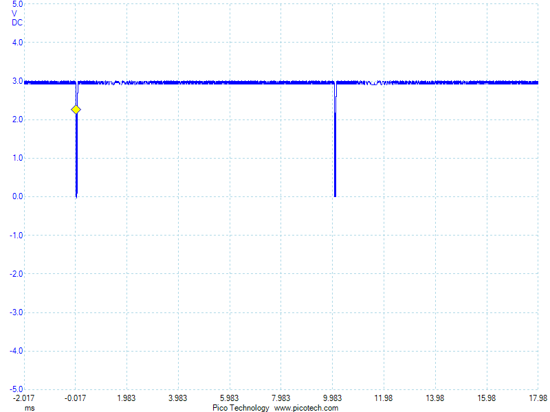
I assume I’ll have to use the 16-bit counter for this. How many clock cycles occur in one revolution? The clock runs at 16 MHz. 16,000,000 / 43.75 = 365,715 clock cycles. Does that fit in a 16 bit counter, which is 4 hex digits? 365,715 = 0x59493. No. So I have to enable a prescaler. According to the 328 datasheet, my options are /8, /64, /256, or /1024.

Will the /8 prescaler allow this value to fit? 0x59493 / 8 = 0xB292. Yep!

Since I used the 16 bit counter to get the revolution time, I have to use an 8 bit timer for the angle timing. How many angle slices should I use? To start, I’ll try 512 because it’s a power of 2, making it fast and easy to divide and it sounds like it may be a good divisor for the clock cycles. How many clock cycles does that leave for each angle? 365,715 cycles per revolution / 512 angles per revolution = 714 cycles per angle. This doesn’t fit in 8 bits, but if we enable the /8 prescaler, 714 / 8 = 89, which does fit in 8 bits, meaning this is still practical. (Note that these numbers don’t evenly divide, so I’ll have to play with it on the hardware to see how well this works.) This also means that I have 714 instruction cycles for each angle. We have to clock 16 bits out of SPI to set the LEDs. The SPI clock runs at half the processor clock, so 16 bits takes 32 instruction cycles to clock out. That still leaves 682 instruction cycles to do the calculation of the new LED states. Still sounds like we’re in the realm of possibility  so I’ll start testing it. If it doesn’t work, I can always drop down to 256 angle slices which will give me double the time to calculate each LED state.

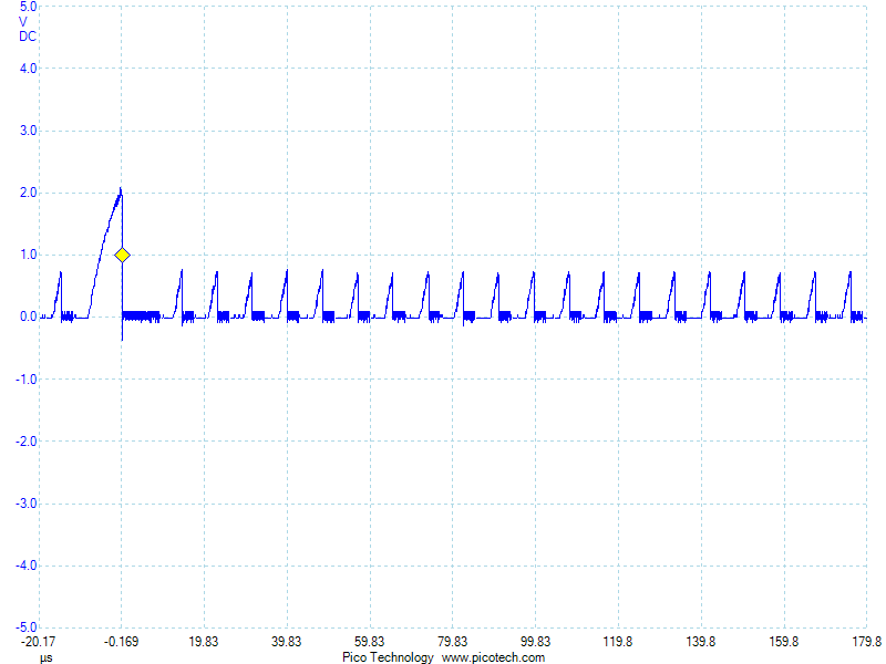
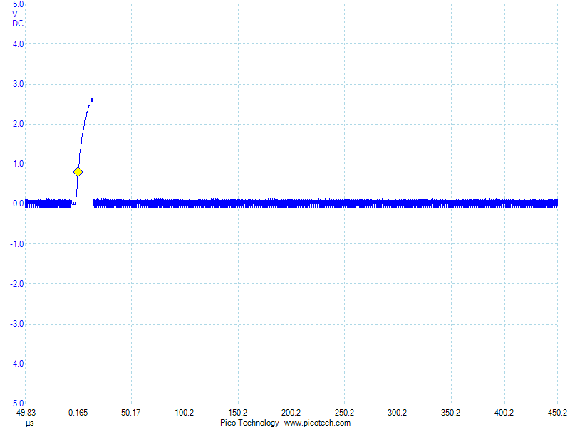
Anyway–that’s a lot to deal with, but I haven’t actually done anything with the counter on the 328. So, to start with, I’ll setup the counter and find out if my calculations are correct about the clock cycles per revolution. I wish I had my IR output working so I could wirelessly send counter value, but the IR out also requires a counter/timer and I just don’t have that setup yet.

But, I have 16 LEDs available, so I can output a 16 bit value on those! My first test will:

  • Setup the 16 bit counter with a /8 prescaler
  • Each time the start position is detected in the ISR, save 16 bit counter value, then reset the counter to 0
  • In the main loop, if the saved counter value is not 0, set the LEDs to the new value, then set the saved value to 0.


Working board!

After being out of town for a few days, I was finally able to get board to the board and add a decoupling cap:

Ugly, but it works!

Ugly, but it works!

I tried putting a little super glue down to hold it in place, but that didn’t harden fast enough and ultimately caused more problems than it was worth. Despite what it looks like, I did use some actual wire (actually spare leads cut off from some through hole parts) in addition to the solder. It’s ugly, but it does actually solve my problem! No more spurious interrupts! Now I cat get my entire binary pattern displayed!

Binary Pattern

I still have my 1 ms delay in there from my testing to see if that fixes the interrupt problem, so that’s why the pattern stays constant around the magnet. But the rest of it looks great! Now I can finally get to programming REAL patterns!

More discoveries

I figured that even if the hall effect sensor glitches when switching a bunch of LEDs in the presence of a magnetic field, I could still make use of this board by not switching anything while the hall effect sensor is active. So I changed the code to display a binary pattern. When the hall effect interrupt is triggered, hold the current LED display for 1 ms to give the board time to spin past the magnet, then reset the pattern to 0.

As soon as I turned on the board, I could tell there was a problem. No more than 6 LEDs ever lit up, even with no magnet to reset the pattern. But, all the LEDs that were flashing were going too fast to clearly see what was happening so I spun it around to see what it looked like:

Binary Pattern Glitch

Once again, I am impressed by how fast I can switch the LEDs and how small they appear when I do. (Look at the outer most LED–you may have to view the full size image to even see the individual pixels.)

But from this, I can see what’s happening. Each time I have 5 LEDs on, then switch them all off (and in this case, switch one more on), I get a false hall effect pulse. This is seen in the pictures by the single LED holding for 1 ms, then resetting back to the beginning of the pattern.

So, I can’t really do anything interesting with the board until I fix this problem with the current. My first attempt at putting on some filter caps failed, so I need to find a better way to do it or work on another board design that has the filter caps included in the layout.


Random thoughts

I had some home remodeling projects to do this weekend, so I haven’t had much chance to work on the spinner this weekend. I do have a couple thoughts to share about the project though.

  1. I wish I had put more testpoints on the board. I had thought about that when doing the layout but couldn’t think what I should break out. I wish I had thought harder since the hall effect sensor was a clear choice. I’ve had problems with that on every single board I’ve made, so it would have made total sense to break that out. SPI would have been another easy choice since that’s how I communicate with the LED driver. But, since I put the ICSP header on there, I did actually have that broken out! That was probably just luck.
  2. I had thought about putting a DC-DC boost converter on the board. That way I could have used a single AAA battery and boosted it to 5V. At the time I didn’t do that because I hadn’t designed or tested a boost converter and didn’t want to take the extra time to do that and because I calculated that it wouldn’t have saved me any money on the PCB printing. I thought about picking a different battery, but I didn’t know of a commonly available one that was smaller and provided any current capabilities.Now I wish that I had done that though. If I had boosted it to 5V, then I could have directly used my FTDI 5V USB serial cable. As it is now, to use that, I hook 5V on the ICSP header and turn off the battery when I’m using the serial port. It would have been way more convenient not to have to deal with that. My next design will incorporate a boost converter. Although, now that I think about it, I am having trouble with the LED driver pulling so much current that 2 AAA batteries have problems. I don’t know what would happen if I tried this with a single AAA and boost converter. I need to do some experiments…
  3. It has worked out very well that I put the Arduino bootloader on the processor though. Makes it very easy to compile and upload–almost just like using a regular Arduino. The only reason it’s not the same is because my FTDI cable doesn’t break out the DTR signal that the Arduino software uses to reset the board. At the moment, I have to manually reset it for each upload and sometimes I get the timing wrong. But, it is still very handy to press the one “compile and upload” button and have it all happen! MUCH easier than back in the day when I was playing with 8051s and had to use a standalone EEPROM programmer and physically switch chips each time!

That’s all for now. More updates as soon as I figure out how to fix or workaround my current problems…


Problem discovered

I posted about my problem on reddit yesterday and got a lot of very helpful suggestions. The top voted answer was that switching all those LEDs caused a current transient that shows up in my hall effect line. It probably doesn’t help that I have a long thing Vcc line to the hall effect sensor and that I have a long thin output line from the hall effect sensor running directly under the LEDs and a huge Vcc plane (which is only there due to my poor board design).

I proved this theory by first lifting Vcc from the LED driver, preventing it from pulling current, but keeping everything else the same. This eliminated the problem! Then I realized I didn’t really need to do that–I could have just as well initialized the LED driver to turn all the LEDs off. But finally I realized that probably switching 2 LEDs (turning 1 on and one off) wouldn’t draw too much current, so I soldered Vcc back on and gave that a try:

Hall effect sensor works exactly as expected now with no glitches!

Hall effect sensor works exactly as expected now with no glitches!

Works perfectly, thus providing even more evidence that’s what the problem is.

Now I just need to find a way to get some more caps added on there…

Making (slow) progress

I was able to figure out what’s going on with my hall effect problem last night. I narrowed things down until I discovered that the BLANK line output (pin 8 on Arduino, PB0 on a 328p) is interfering with my hall effect input (pin 2 on Arduino, PD2 on a 328p). The test that proved this was one where I have just this:

void loop() {

digitalWrite(BLANK, HIGH);

digitalWrite(BLANK, LOW);

}

When I look at the hall effect input pin on the scope while holding a magnet near it, I see this:

SpinnerHD-justBlankPulse


I’m not sure why one pulse is much bigger than the rest. Perhaps that’s when the hall effect interrupt gets serviced and interrupts the loop. I just happened to have my trigger point at 1V, so it was triggering on the big pulse.

But, I don’t know WHY this is happening. My meter doesn’t show any continuity between these pins. Looking at the traces, they’re both long, but nowhere close to each other. At the moment, I have no idea what’s going wrong.

Next problem…

Now that the board mostly works, I’ve run into the next problem. The hall effect sensor isn’t working like I expect. I’ve got it on a pullup resistor and expect that it stays high most of the time, then in the presence of a magnetic field, it goes low and stays the whole time. This is exactly how it worked when I prototyped it on an Arduino. But on this board, it pulses while next to a magnet:

SS351-Mistrigger2


Zooming out a little, I can see that it happens almost exactly every 10 ms:

SS361-MisTriggerTiming


It looks like something else is trying to drive that line every 10 ms. But running the exact same code on the Arduino doesn’t do this. And nothing else should be on that line. Maybe it’s a PCB error. Maybe it’s because of the modifications I had to make to fix the board. Maybe I overheated the chip while mounting it. The chip is a little different. I prototyped with the SS451 because it fits in a breadboard. Then I used the SMD SS351AT on my PCB. They really shouldn’t behave that differently though. It also mistriggers when a magnet is not present:

SS351-MisTriggerTiming2

I don’t know what’s going on here. I need to think about this…

While I’m figuring that out, I can do some other tests though. First a quick balance check:

HDSpinnerBalanceTest


The actual balance point is actually a little bit forward from where the hole is drilled, but not by too much. It should still work. My first test alternates each pixel on and off as fast as possible.

Pixel speed test


The main reason I used direct pin outputs for my last spinner is because I was worried sending SPI data wouldn’t be fast enough. But this is extremely impressive! Look at the spacing of those pixels. WOW! Looks like I needn’t have worried! I can’t wait to fix the hall effect problem so I can see what I can do with this! Here’s a closeup for more detail:

IMG_0742