
It may seem like I’ve been spending all my time on the spinner project, but I have actually been spending some time on the electromagnetic tests as well. After my initial tests to wrap an electromagnet a few weeks ago failed, I realized I needed something with some fixed dividers. I came up with a plan in my mind, but then needed to model it so I could print it at Shapeways.
Based on their software recommendations, I started with Blender. I played with it for several days, going through a few tutorials, but then failed to figure out how to get boolean operations to work right or how to align objects. After several days, I still couldn’t create a hollow tube. Then I realized this really isn’t the right tool for the job. It’s not designed for CAD work.
Looking for CAD software, I started with OpenSCAD. Within a few minutes, I had a tube with the exact dimensions I wanted. Shortly thereafter, I even had my dividers:
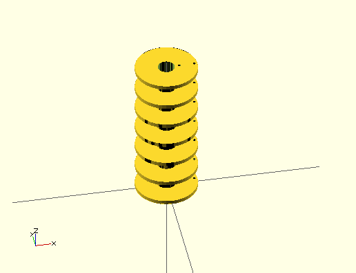
First design of the electrotest on OpenSCAD
I then uploaded this to Shapeways and found that it does work on there! So I spent another week trying to add mounting points for a PCB on top and a separate mounting bracket on the bottom. During this phase I ran into problems with OpenSCAD:
- I can’t set the plane at which drawing cuts out. At the scale I’m working on, I can’t zoom in close enough to see what’s happening because rendering cuts out. I don’t remember what this is called, but I saw on one of the Blender tutorials how to fix the problem there.
- Figuring out how to draw things is annoying. I can’t just specify coordinates. I have to translate the coordinate system and then draw about the origin. I have to keep thinking in reverse that way.
- You can’t use the mouse to draw. I had to figure out how to draw a 3D space by visualizing the coordinates, typing them in by hand, then visualizing all the triangles needed to draw that and enter them in clockwise order.
- The rendering routines aren’t very good. As you rotate, planes go directly from color to black as it decides they’re in shadow.
- There’s no way to measure to verify that I’ve done everything correctly.
So I decided to try another program: BRL-CAD, an open source CAD program developed and used by the government. I’m still trying to figure this one out. It’s not quite as easy to use as I’d hoped. I’m not sure that it has the mouse drawing that I’d like, but it does at least let me draw things at specific coordinates. More updates on that as I test more…