Sculpteo Shipping FAIL

The package from Sculpteo finally arrived today and now I see what took so long:

Stamp on my package from Sculpteo

Stamp on my package from Sculpteo

That’s right–despite having an office in San Francisco, they printed my piece in France and shipping it from there! Obviously this is not an option for faster shipping than Shapeways. It is cool to see the completed piece just as I designed it though:

Sculpteo Printed Piece

But, it looks like I’m still trying to find a reasonable way to get things printed fast and cheap.


Shipping from Sculpteo

I was wrong about shipping from Sculpteo. They did send me email this morning telling me that my order has shipped. Of course, there is no tracking number as they already told me. But I’m hoping that regular mail will get from the Bay Area in a couple of days. Their projection when I ordered was as late as April 25th, so I certainly hope it doesn’t take that long. Good to know it’s on the way…

More tests

Since it will be  a while before my new coil design is ready, I took the take to get my test platform setup:

ElectroMagnet Test Platform

This gives me a switch so I can turn each coil on and off independently. It also lets me turn them all off and adjust the voltage accurately before applying power to the coils again.

Just like on my spinner platform, these switches made things work much better! I don’t have the coil secured (waiting on my new coil design with mounting points for that), but I was still able to learn some things.

First, using the coil that is slightly larger than the other, I did tests to see how much current I can push through there. And again I kept my temperature probe on the coil so I could monitor if it was getting too hot. Better picture here:

Coil Test Closeup

I ended up with this:

5V 10V 12V 15V 20V
0.64A (84°F) 1.25A (100°F) 1.40A (120°F) 1.60+A (HOT) 2.0+A (170+°F)

My notes from things I tested:

  • Switching between the two coils, I was unable to get the nail to move back and forth, no matter what voltage I used. (I later learned this may be due to the length of the nail.)
  • It takes a long time for the coils to cool. Even brief pulses at 15V cause the temperature to shoot up to 130°.
  • I tried using a scale to measure how much force the electromagnet exerts. Most of the tests, I got absolutely nothing. While playing with 20V, I noticed that I got a strong pull right when the end of the nail was coming out of the coil. I measured that at 60 grams. (I’m not sure what force that is–I suppose the equivalent force that it takes to pull 60 grams against gravity.)
  • At 10V, there is no noticeable pull on the nail. I’m not sure how little I can feel, but I’m sure this is quite light.

Checking in with the Shapeways design specs, I see that the flexible plastic is only heatproof to 176°F. This is clearly a problem as it quickly gets that hot at the minimum voltage that I felt a significant pull.

I need to try either other wire sizes, better heat sinking materials, or a different design.

Revised coil design

I had the day off of work today, so I finally had a chance to work on my new coil design with connections on the bottom so it can be mounted and tabs on the top so I can mount a  PCB.

After reading about other people using SketchUp, I decided to try that. I do like a lot of the features, like being able to directly manipulate the design and measure to make sure things are aligned exactly like I expect. But, I also ran into problems. I wasn’t able to do difference operations on cylinders. Difference operations aren’t directly supported anyway, but once I tried to an intersection with a cylinder so I could remove parts, things get really messed up. I also had problems with simpler shapes because SketchUp isn’t a solid modeling tool, so I wasn’t sure if things I was creating would be solid or just exterior walls.

But, SketchUp was great for being able to sketch my design so I could model it in OpenSCAD:

ElectroDesign-Iso-Sketchup


Once I had the dimensions all figured out, it was much easier to go step by step and add all the design features I wanted. This went much more quickly than when I tried it before without doing a SketchUp first:

ElectroDesign1-Iso


I also did some research to find a company other than Shapeways where I could get it printed cheaply, but not have to wait for shipping from the East Coast. I did find Solid Concepts which has an office in San Diego! Perhaps I can just go pick it up in a day or two! Sadly, of all the materials I tried, the cheapest I could find still cost $80 for this piece, which is over 10 times greater than what Shapeways charges. A little more research and I found Sculpteo. They’re not in San Diego, but at least they’re in California. Costs under $8 and says it ships in 4 days! So, I decided to give them a try. The cheapest shipping still cost $6 but comes with absolutely no tracking information. As far as I can tell, Sculpteo doesn’t give any information about when my design actually ships (unlike Shapeways), so I just have to wait and see when it arrives. I’ll hold off judgement on them until I see how long it ends up taking…

First real tests

I didn’t have a good plan for how to wind this thing, other than that I figured my drill was the best option since I can run it really slow. Digging through my tools from my Harbor Freight rotary tool, I found an attachment with a nice rubber piece a quarter inch in diameter. Looks good at first:

Ready to wind


Then I put the spool of wire on a dowel and put the dowel between my sandals and toes to hold it in place. This actually worked better than I expected! I wound the first section really easily and didn’t have any problems with anything breaking. One the second one, the rubber piece started slipping, but I managed to salvage it enough to finish off the second coil:

Wound coils


Looks like I do need to find a way to make sure the coils are the same size. I didn’t have too much time, but I did a quick test. The resistance on the first coil measures out to ~6 Ω, which is about what I expected. I should be able to run at 6V and get 1 A through it without any problem. This time I was prepared for the coil to get warm, so I setup my meter to monitor the temperature.

At 5V, I could feel a little pull the nail I am using as my shaft right now. I’m sure I can find something better, but that’s all I have that fits in there right now. At 10V, I could feel a significant pull on the nail, but then the temperature jumped up to 100°F. The coil didn’t actually feel warm, but I shut it all down because I didn’t want to risk destroying it.

Temporary test plan

I figured I really should test all this before spending a ton of money on it, so I walked around Home Depot and found a tube with a 1/4″ outside diameter. The only magnetic thing I could find to fit inside was a #16 nail, so I bought some of those.

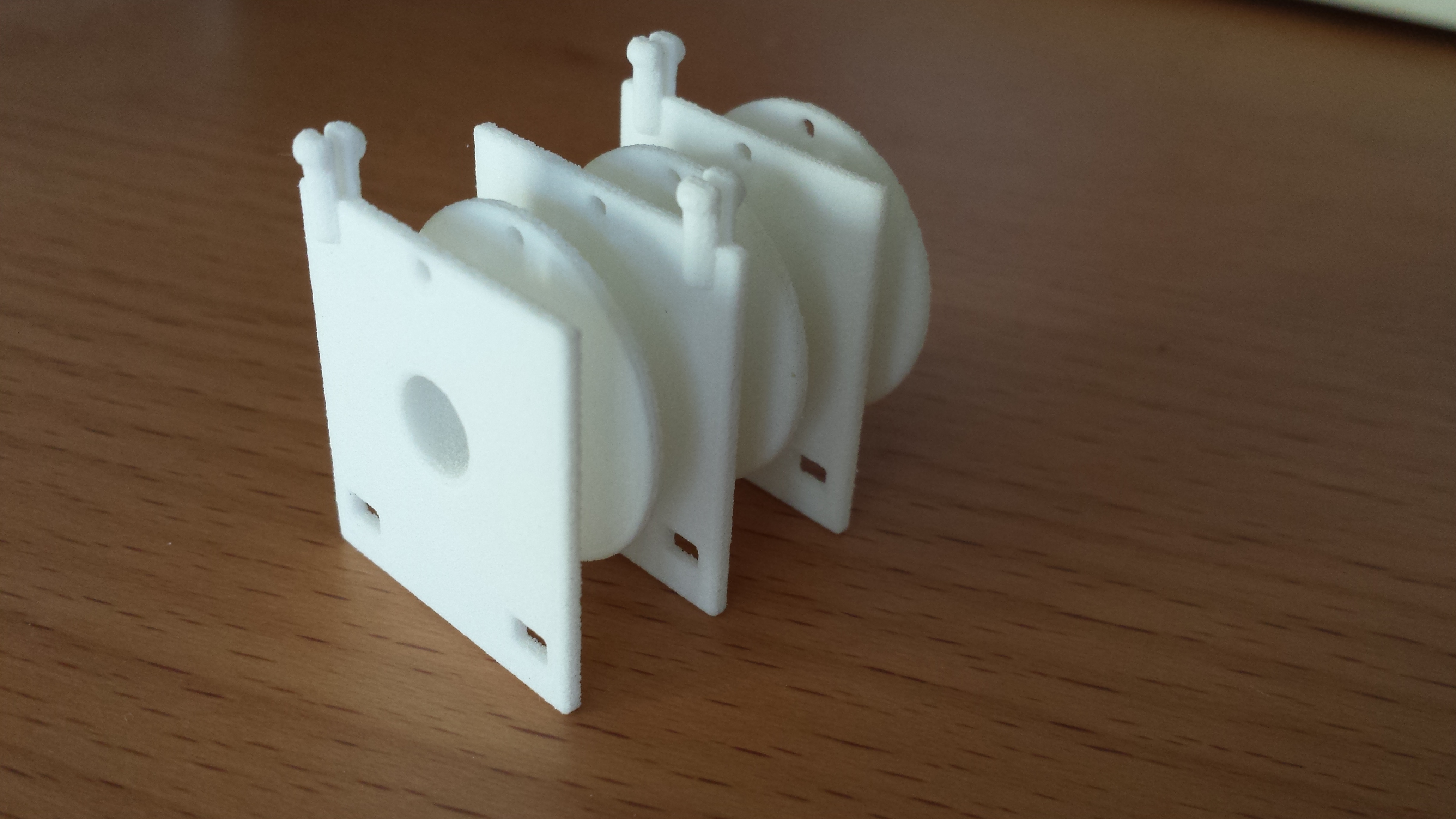
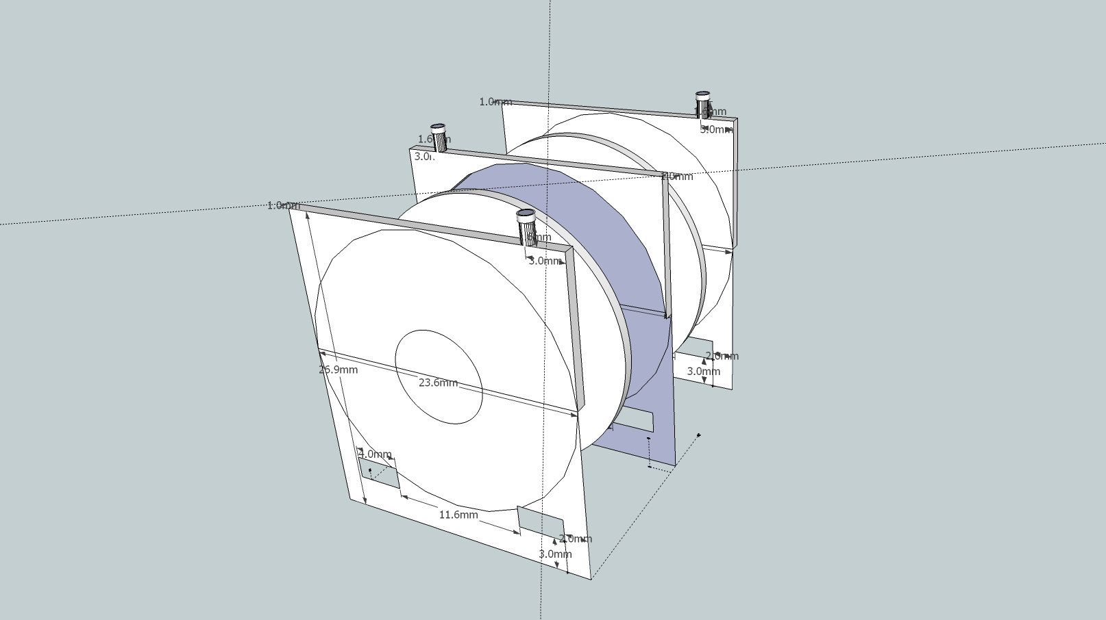
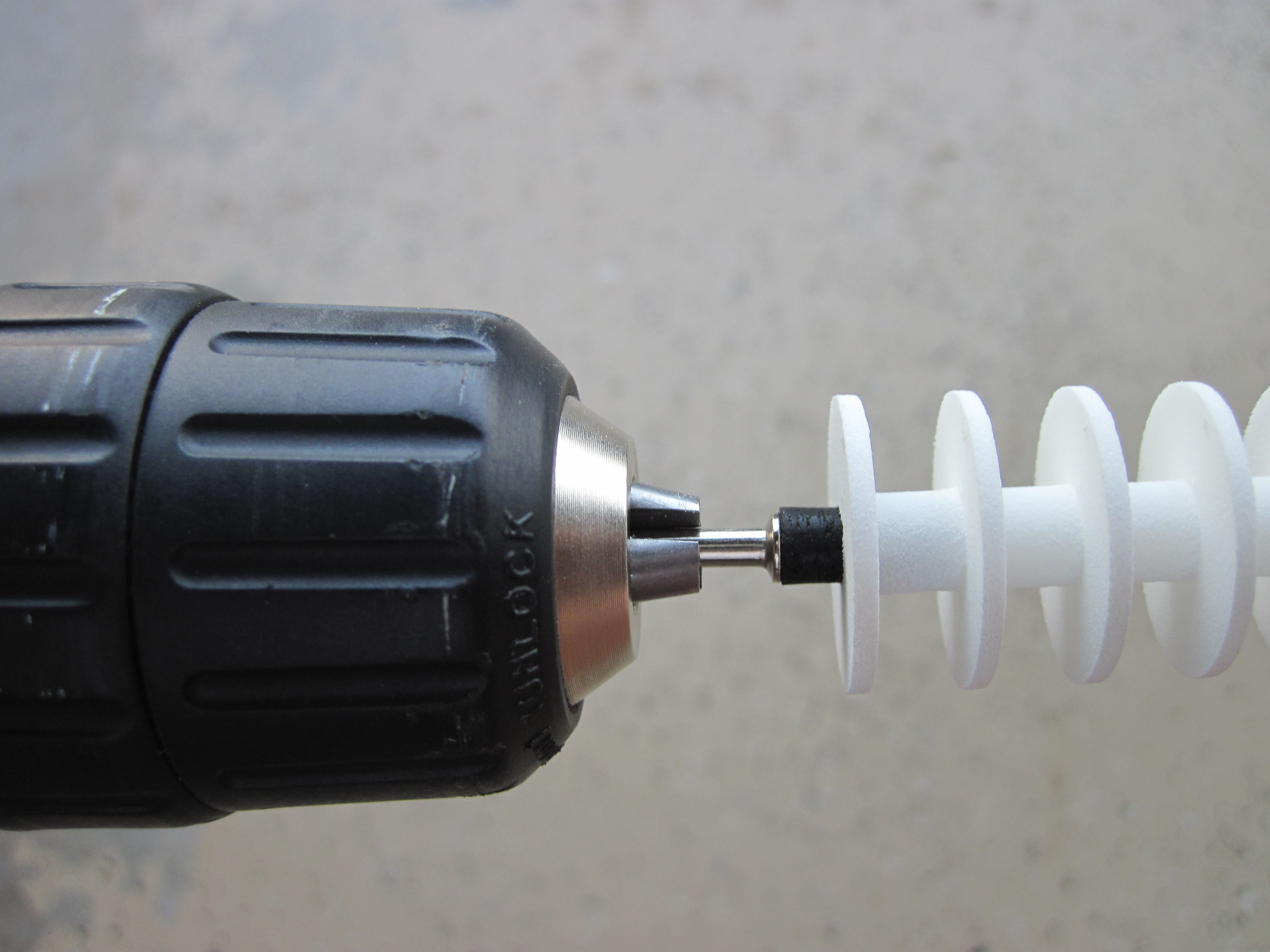
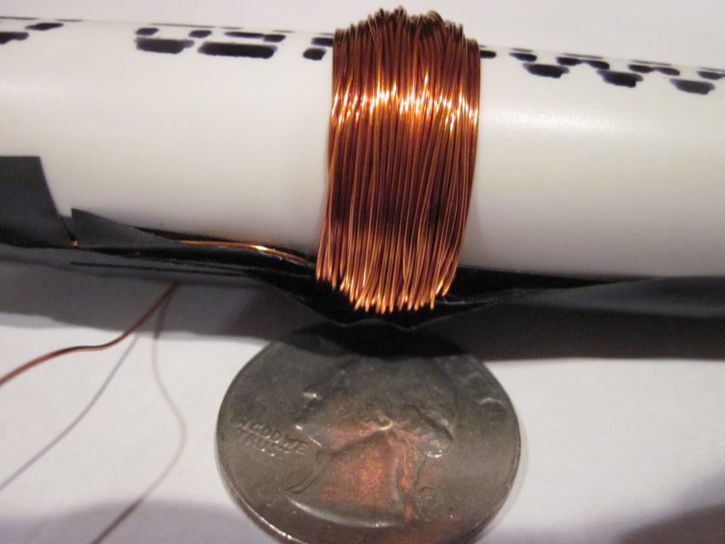
So I cut out some 1″ square dividers, cut a 1/4″ hole in the middle, put a couple of small holes to run wire through, and put them on the tube:

Proto Tester

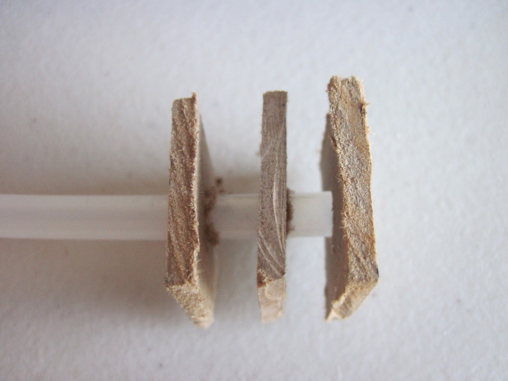
I figured it needed some extra support, so I put superglue around each of the pieces where they attach to the tube.

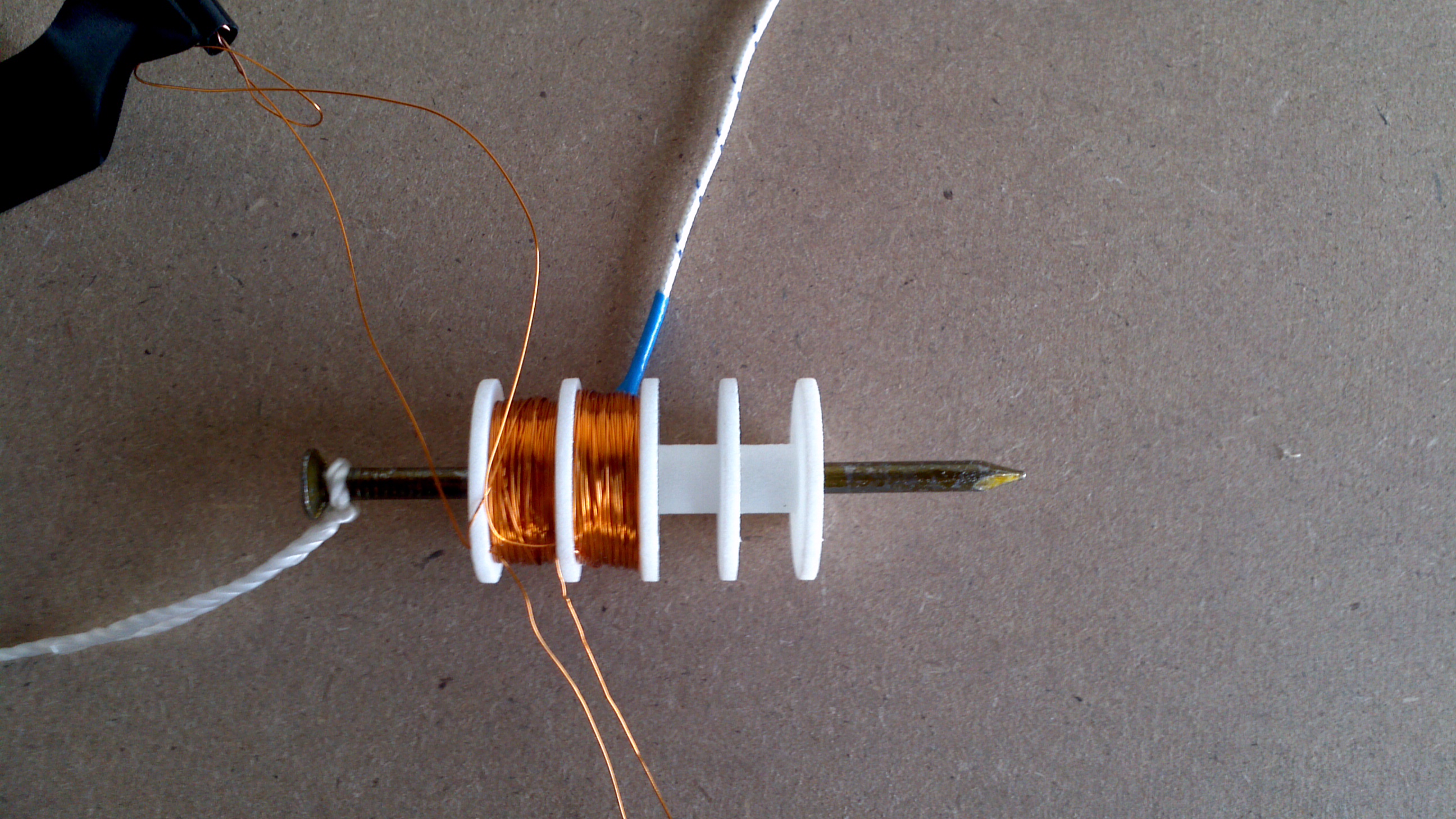
A couple days later, I tried winding 30 gauge wire on one of them. It worked for a while, but then the end cap popped off. Next I noticed that the middle divider had been moving as well. Clearly the superglue wasn’t holding the dividers. So, I held the endcap on, put a bunch of superglue on the coil to fix that in place and let it sit.

Proto Test 1

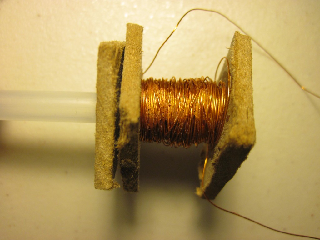
The next day, I stripped the ends of the wire and measured the resistance. It came up right around 5 Ohms, which is just what I was shooting for. This means I can run it up to 20 V, which puts 4 Amps through there. According to a chart I found, 30 gauge wire can take up to 10 Amps for up to 10 seconds, so 4 A shouldn’t be a problem.

This is a perfect use for my new power supply! I hooked the coil up to it, set it for 5 V, saw 1 A going through the coil and played with a nail in the tube. It was certainly getting sucked in, but not very strongly. So, I bumped it up to 20 V and felt the nail get pulled in more strongly. As I played with this a little more, suddenly the coil started smoking. I odor made me think it was actually the superglue burning, but I quickly shut everything down and haven’t touched it again in a week. Hopefully I’ll soon get back to this…


Electrotests

It may seem like I’ve been spending all my time on the spinner project, but I have actually been spending some time on the electromagnetic tests as well. After my initial tests to wrap an electromagnet a few weeks ago failed, I realized I needed something with some fixed dividers. I came up with a plan in my mind, but then needed to model it so I could print it at Shapeways.

Based on their software recommendations, I started with Blender. I played with it for several days, going through a few tutorials, but then failed to figure out how to get boolean operations to work right or how to align objects. After several days, I still couldn’t create a hollow tube. Then I realized this really isn’t the right tool for the job. It’s not designed for CAD work.

Looking for CAD software, I started with OpenSCAD. Within a few minutes, I had a tube with the exact dimensions I wanted. Shortly thereafter, I even had my dividers:

First design of the electrotest on OpenSCAD

First design of the electrotest on OpenSCAD

I then uploaded this to Shapeways and found that it does work on there! So I spent another week trying to add mounting points for a PCB on top and a separate mounting bracket on the bottom. During this phase I ran into problems with OpenSCAD:

  1. I can’t set the plane at which drawing cuts out. At the scale I’m working on, I can’t zoom in close enough to see what’s happening because rendering cuts out. I don’t remember what this is called, but I saw on one of the Blender tutorials how to fix the problem there.
  2. Figuring out how to draw things is annoying. I can’t just specify coordinates. I have to translate the coordinate system and then draw about the origin. I have to keep thinking in reverse that way.
  3. You can’t use the mouse to draw. I had to figure out how to draw a 3D space by visualizing the coordinates, typing them in by hand, then visualizing all the triangles needed to draw that and enter them in clockwise order.
  4. The rendering routines aren’t very good. As you rotate, planes go directly from color to black as it decides they’re in shadow.
  5. There’s no way to measure to verify that I’ve done everything correctly.

So I decided to try another program: BRL-CAD, an open source CAD program developed and used by the government. I’m still trying to figure this one out. It’s not quite as easy to use as I’d hoped. I’m not sure that it has the mouse drawing that I’d like, but it does at least let me draw things at specific coordinates. More updates on that as I test more…

Test platform

I got a little more done this weekend. I got my test platform created:

ElectroTestPlatform


You can see here that I ran out of corner pieces. It’s not quite as stable as I’d like, but it’ll do. I also make a trip to Home Depot looking for hardware to be able to make some prototypes. I didn’t find exactly what I wanted, but left with a few potential options. I’ll also take a look at making my own 3D modeled part for testing.

Home Depot

I love Home Depot. It’s great for all my projects. I’ve spend a lot of time lately trying to find a simple toggle switch that can handle up to 5 Amps. I finally found one I liked that’s about $6 a piece and was about to order some, but held off. Then I stopped by Home Depot just to get some PVC to wind an electromagnet around. I figured I’d look through the electronics isle just in case they had a switch. Suddenly, inspiration struck! A cheap switch that can handle at least 5 A? A light switch of course–for only 69 cents!!:

Cheap lightswitch I found at Home Depot that looks like it will meet my needs and pretty cheaply

Cheap lightswitch I found at Home Depot that looks like it will meet my needs and pretty cheaply

Okay, it does say 15A 120 VAC only, but I assume that will also work fine with <12 VDC @ 5 A. I did also pick up a 1/2″ PVC pipe so I could start on my first electromagnet.

My goal was to use 26 AWG wire, 13 turns per layer (to make a coil 1/4″ long) and 10 layers. As it turns out, winding these is rather difficult, especially without a form. I tried to wind it close to the edge of the pipe so I could see if a 1/2″ ball bearing could be picked up by it, but I couldn’t get enough tape on the edge to keep everything from falling apart. So, I decided to wind it further up the pipe so I could use a lot more tape. Without any side pieces to hold the shape, it’s difficult to get each layer of wires to stack on the previous. But I did eventually get approximately 5 layers done:

My first attempt at winding an electromagnet

My first attempt at winding an electromagnet

Figure that’s good enough for now, so I’ll see what it can do. I did a quick test with the meter to find about 1.8 Ohm resistance. Since that’s not going to limit the current much, I didn’t want to try it with a real power supply and instead started with a 9V battery. I got some sparks off it, so I went for a magnetic test. Placed my ball bearing close to it and did see it move! Not far or far, but it did move. I tried putting the ball bearing inside the PVC, as my current goal is to hold it in there. That test failed though. I couldn’t get the ball in the right position at the same time as keeping the the power on to the coil. And, of course, one problem with a PVC pipe is that it’s not transparent, so I can’t see what’s going on inside. One of my next goals is to find something I can see inside of for this… I wish I had been able to wind the coil closer to the end of the pipe so I could try sucking the ball bearing into it. Maybe after I work on my winding technique, I can try that again later.