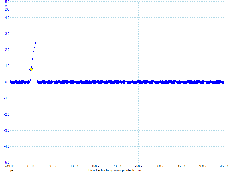
Now that the board mostly works, I’ve run into the next problem. The hall effect sensor isn’t working like I expect. I’ve got it on a pullup resistor and expect that it stays high most of the time, then in the presence of a magnetic field, it goes low and stays the whole time. This is exactly how it worked when I prototyped it on an Arduino. But on this board, it pulses while next to a magnet:
Zooming out a little, I can see that it happens almost exactly every 10 ms:
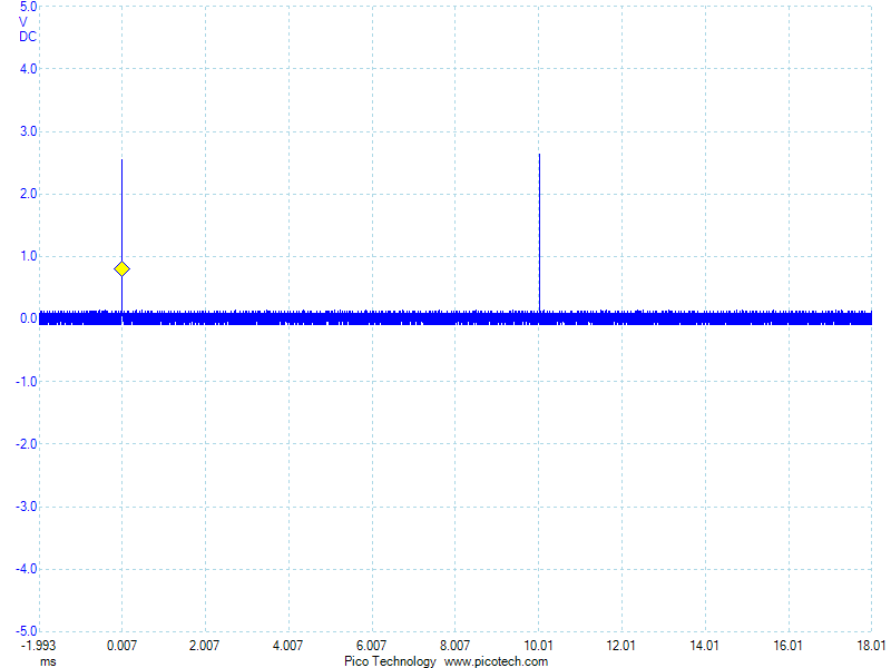
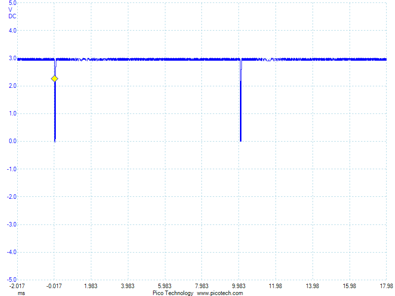
It looks like something else is trying to drive that line every 10 ms. But running the exact same code on the Arduino doesn’t do this. And nothing else should be on that line. Maybe it’s a PCB error. Maybe it’s because of the modifications I had to make to fix the board. Maybe I overheated the chip while mounting it. The chip is a little different. I prototyped with the SS451 because it fits in a breadboard. Then I used the SMD SS351AT on my PCB. They really shouldn’t behave that differently though. It also mistriggers when a magnet is not present:
I don’t know what’s going on here. I need to think about this…
While I’m figuring that out, I can do some other tests though. First a quick balance check:
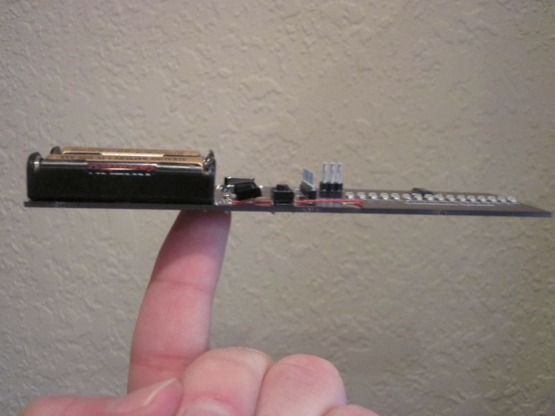
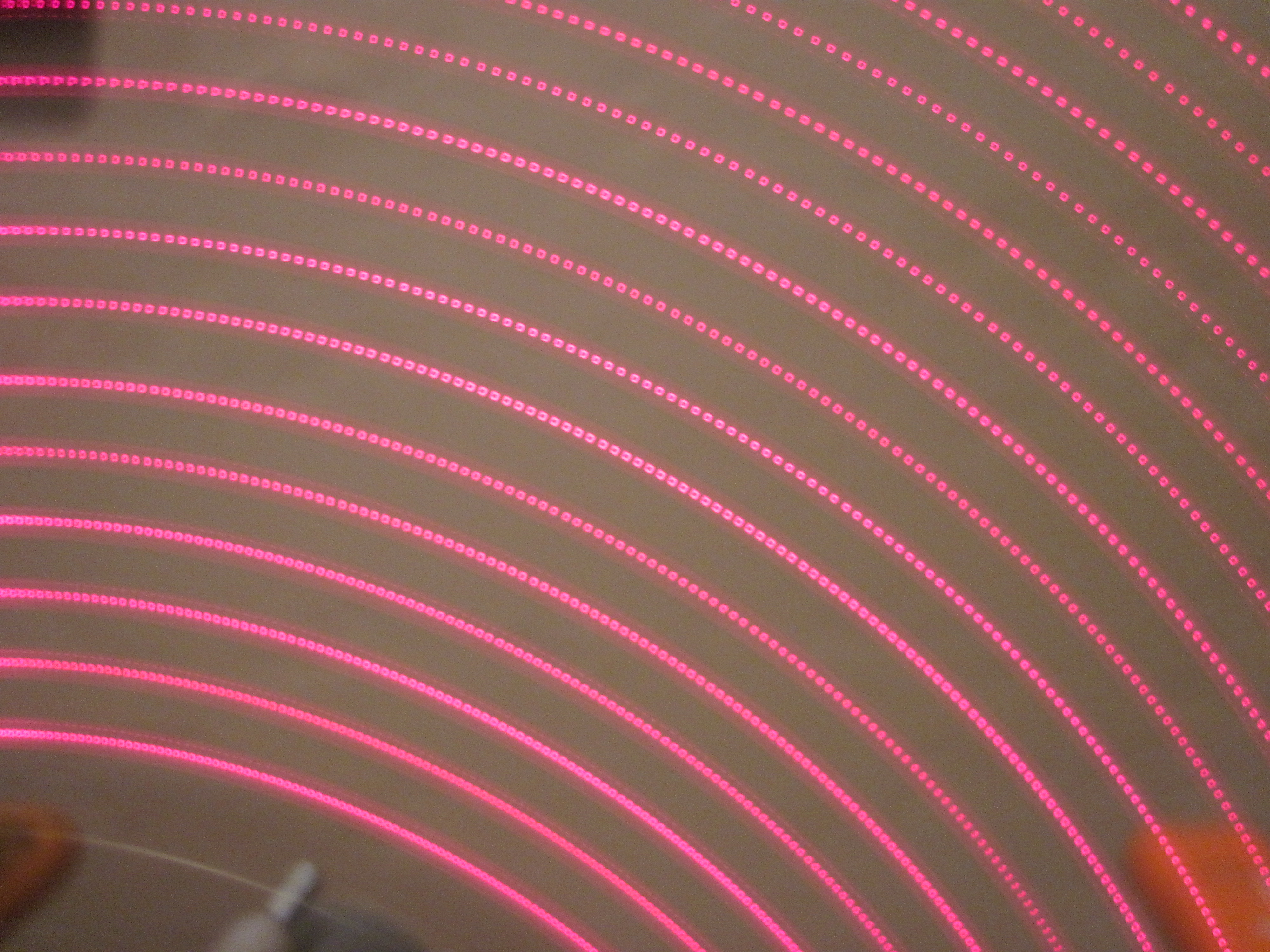
The actual balance point is actually a little bit forward from where the hole is drilled, but not by too much. It should still work. My first test alternates each pixel on and off as fast as possible.
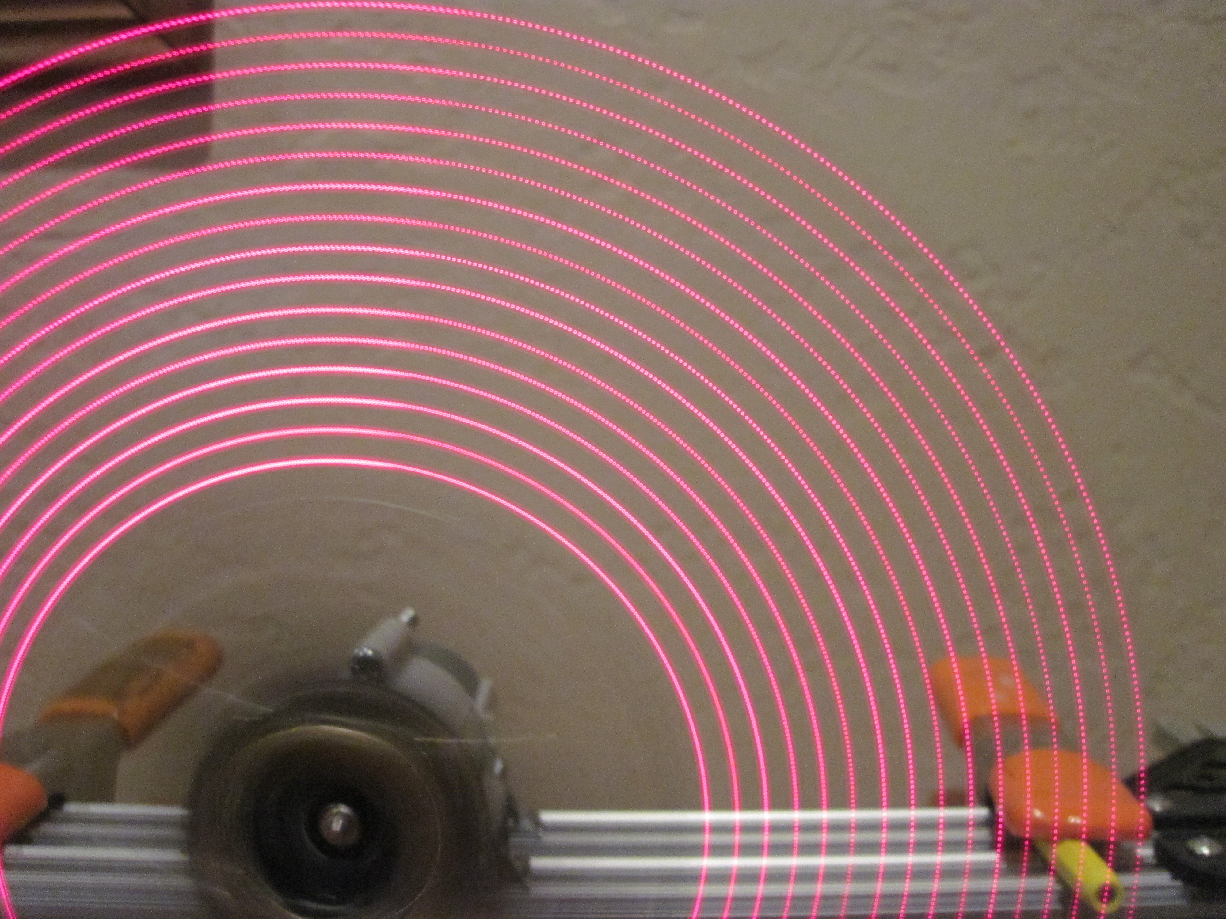
The main reason I used direct pin outputs for my last spinner is because I was worried sending SPI data wouldn’t be fast enough. But this is extremely impressive! Look at the spacing of those pixels. WOW! Looks like I needn’t have worried! I can’t wait to fix the hall effect problem so I can see what I can do with this! Here’s a closeup for more detail: