
I was able to figure out what’s going on with my hall effect problem last night. I narrowed things down until I discovered that the BLANK line output (pin 8 on Arduino, PB0 on a 328p) is interfering with my hall effect input (pin 2 on Arduino, PD2 on a 328p). The test that proved this was one where I have just this:
void loop() {
digitalWrite(BLANK, HIGH);
digitalWrite(BLANK, LOW);
}
When I look at the hall effect input pin on the scope while holding a magnet near it, I see this:
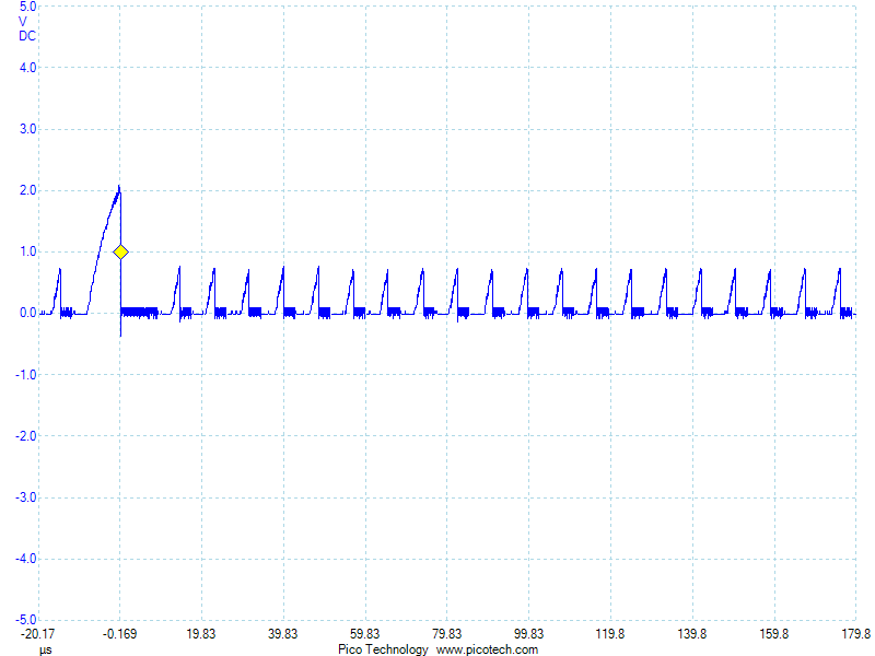
I’m not sure why one pulse is much bigger than the rest. Perhaps that’s when the hall effect interrupt gets serviced and interrupts the loop. I just happened to have my trigger point at 1V, so it was triggering on the big pulse.
But, I don’t know WHY this is happening. My meter doesn’t show any continuity between these pins. Looking at the traces, they’re both long, but nowhere close to each other. At the moment, I have no idea what’s going wrong.