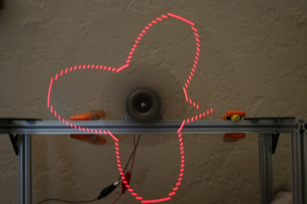
Now that the board is working, I thought I’d try a more interesting pattern, so I started with a sine wave. I wrote a quick python script to generate a nice looking sine wave:
1 2 3 4 5 6 7 8 9 10 11 12 13 14 15 16 17 18 19 20 | import math rows = 16 columns = 512 print "#define SIN_PATTERN_MAX %d" % columns print "const int sinPattern[SIN_PATTERN_MAX] = {" for x in range(0,columns): realx = 2 * math.pi * x / columns val = (rows / 2) + (rows / 2) * math.sin(realx) y = math.trunc ( val ) if y > (rows - 1): y = rows - 1 #print '%*s' % ((y + 1), '*') print '0x%04X, ' % (1<<y), if (x > 6 and (x - 7) % 8 == 0): print print "};" |
Looks great on the console (using that commented out line), but when I display it on the spinner, it looks terrible:

Sorry–I was lazy at trying to get the camera setup to take this entirely in focus and without extra motion.
Obviously this doesn’t work well at all. I need to add correction for the different distances. I quickly realized that the spinner uses polar coordinates which the things I generally want to display use cartesian coordinates.Clearly what I need to do is convert between them!
In order to do that, for each LED, I need to know the distance from the center and the current angle. The distances are fixed and angles can be calculated. I know when the spinner is at one specific angle (in line with the magnet) and I can use one of the counters to determine how long it takes to go around one rotation. Once I know that, I can split that time into equal parts and use that to calculate the current angle.
Will this plan work? According to the datasheet, my motor runs at 10,500 rpm. I’ve got that on a 4:1 gearing so it runs at (10,500 / 4) = 2625 rpm, which is (2625 / 60) = 43.75 rps.
I assume I’ll have to use the 16-bit counter for this. How many clock cycles occur in one revolution? The clock runs at 16 MHz. 16,000,000 / 43.75 = 365,715 clock cycles. Does that fit in a 16 bit counter, which is 4 hex digits? 365,715 = 0x59493. No. So I have to enable a prescaler. According to the 328 datasheet, my options are /8, /64, /256, or /1024.
Will the /8 prescaler allow this value to fit? 0x59493 / 8 = 0xB292. Yep!
Since I used the 16 bit counter to get the revolution time, I have to use an 8 bit timer for the angle timing. How many angle slices should I use? To start, I’ll try 512 because it’s a power of 2, making it fast and easy to divide and it sounds like it may be a good divisor for the clock cycles. How many clock cycles does that leave for each angle? 365,715 cycles per revolution / 512 angles per revolution = 714 cycles per angle. This doesn’t fit in 8 bits, but if we enable the /8 prescaler, 714 / 8 = 89, which does fit in 8 bits, meaning this is still practical. (Note that these numbers don’t evenly divide, so I’ll have to play with it on the hardware to see how well this works.) This also means that I have 714 instruction cycles for each angle. We have to clock 16 bits out of SPI to set the LEDs. The SPI clock runs at half the processor clock, so 16 bits takes 32 instruction cycles to clock out. That still leaves 682 instruction cycles to do the calculation of the new LED states. Still sounds like we’re in the realm of possibility so I’ll start testing it. If it doesn’t work, I can always drop down to 256 angle slices which will give me double the time to calculate each LED state.
Anyway–that’s a lot to deal with, but I haven’t actually done anything with the counter on the 328. So, to start with, I’ll setup the counter and find out if my calculations are correct about the clock cycles per revolution. I wish I had my IR output working so I could wirelessly send counter value, but the IR out also requires a counter/timer and I just don’t have that setup yet.
But, I have 16 LEDs available, so I can output a 16 bit value on those! My first test will:
- Setup the 16 bit counter with a /8 prescaler
- Each time the start position is detected in the ISR, save 16 bit counter value, then reset the counter to 0
- In the main loop, if the saved counter value is not 0, set the LEDs to the new value, then set the saved value to 0.
