
My first test actually went quite well. The counter worked just like I expected and I got the counter information I wanted:
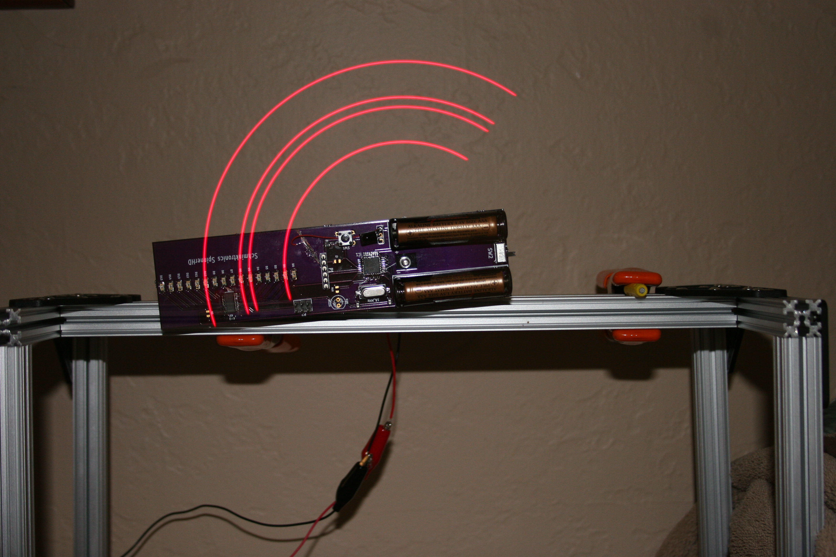
LEDs displaying a binary pattern showing the value of the counter for how long the last rotation took. MSB is the innermost LED.
For this picture, I used a flash, then kept the shutter open a bit. The spinner is actually traveling clockwise, so the trail of LEDs is actually in front of the spinner, not behind it as you would expect.
Anyway–the reason I used the flash was so I could see where each of the LEDs was mounted and could accurately count which ones are off. The MSB is the innermost one, so this counter value is 100011000100000b which is 4620h. This is about 2.5 times smaller than what I predicted. The counter values also change a lot more than I expected. I thought the least significant 2-3 bits would vary, but I actually see the least significant 8-9 bits changing. I know the battery is running low for my battery, so maybe the counter values I’m seeing are accurate.
Here’s the code I used to do this:
1 2 3 4 5 6 7 8 9 10 11 12 13 14 15 16 17 18 19 20 21 22 23 24 25 26 27 28 29 30 31 32 33 34 35 36 37 38 39 40 41 42 43 44 45 46 47 48 49 50 51 52 53 54 55 56 57 58 59 60 61 62 | // Using the spinner board to test 328 counters #include <SPI.h> const int HALL = 2; // PD2 const int BLANK = 8; // PB0 const int LAT = 9; // PB1 const int HALL_INT = 0; // Hall effect interrupt 0 on PD2 (INT0) unsigned int savedCounter = 0; void hallStart(void) { savedCounter = TCNT1; TCNT1 = 0; } void setup() { digitalWrite(LAT, LOW); pinMode(LAT, OUTPUT); digitalWrite(BLANK, HIGH); pinMode(BLANK, OUTPUT); pinMode(HALL, INPUT_PULLUP); // Setup the 16 bit counter TCCR1A = 0; // Turn off output compare modes TCCR1B = 2; // Turn on clk/8 input attachInterrupt(HALL_INT, hallStart, FALLING); SPI.begin(); SPI.setDataMode(SPI_MODE0); SPI.setBitOrder(LSBFIRST); SPI.setClockDivider(SPI_CLOCK_DIV2); // Datasheet says 35 MHz max, so 8 MHz is fine TCNT1 = 0; } void setLeds(unsigned int pattern) { // Blank the LEDS digitalWrite(BLANK, HIGH); // Transfer the data SPI.transfer(pattern & 0xFF); SPI.transfer(pattern >> 8); // Latch the data digitalWrite(LAT, HIGH); digitalWrite(LAT, LOW); // Unblank the LEDS digitalWrite(BLANK, LOW); } void loop() { if (savedCounter != 0) { setLeds(savedCounter); savedCounter = 0; } } |
So, the only way to find out if my counter values are correct is to do the next test:
- Each time I get the hall effect interrupt, read the 16 bit counter (counter 1)
- Divide that by 4096, which is 512 (the number of slices) * 8 (the prescaler), then set that value in output compare A register for 8 bit timer 2. In CTC mode, this gives us an interrupt every time the counter value is matched.
- Each time we get a timer 2 interrupt, increment the slice counter. On slices 0, 128, 256, and 384, turn on all the LEDs for one slice. This should display lines at the 12:00, 3:00, 6:00, and 9:00 positions