
Counter Test 2 works, but not quite right. For some reason, I have to set the prescaler on timer 2 to /64. At first, that worked quite well and gave me exactly what I expected, but by the time I got the camera out, the lines were no longer at 3, 6, 9, and 12:
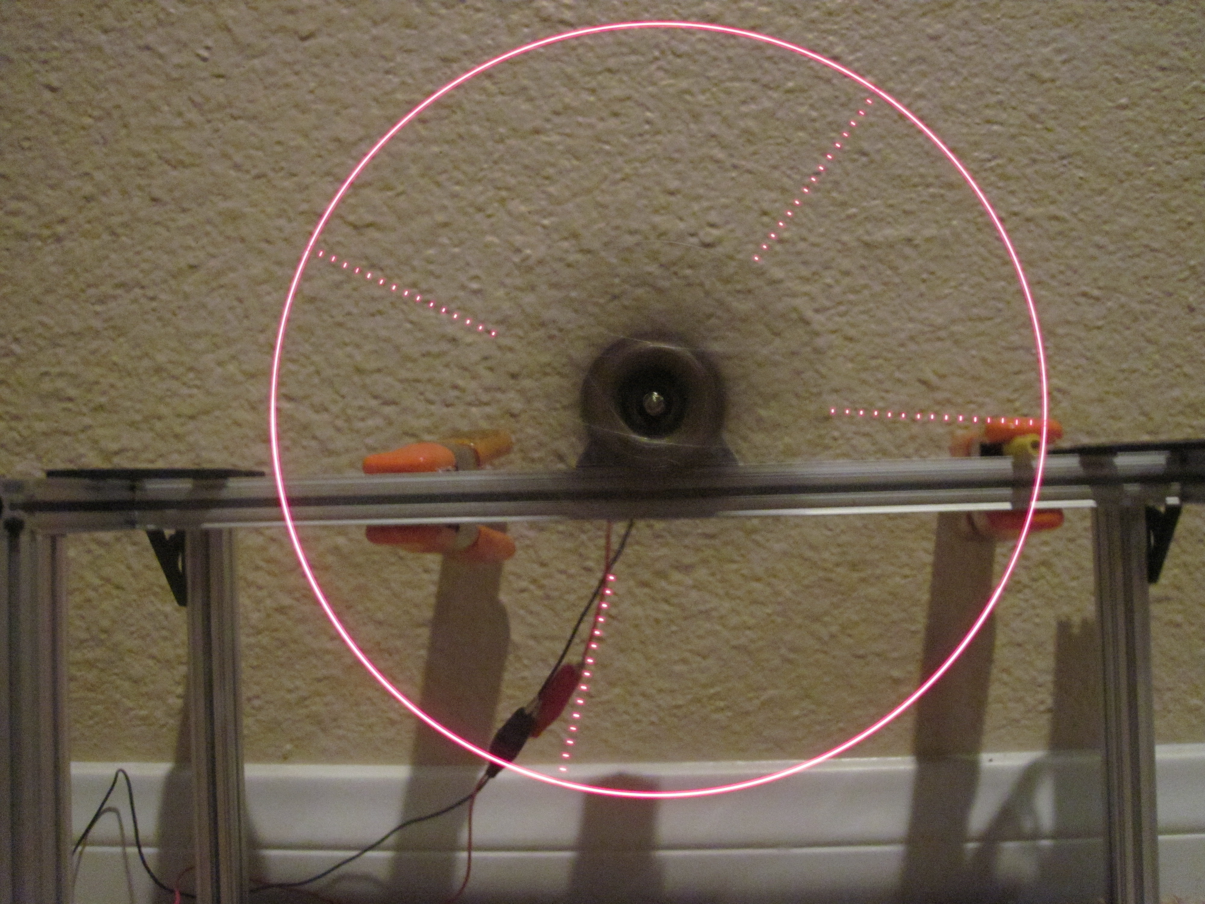
Those lines should be at 3, 6, 9, 12 o’clock. Something’s not quite right…
I suspect my problem here is that I should really be adjusting the prescalers on the fly instead of using the hardcoded values I designed in. My guess is that I’m overflowing what will fit into the 8 bit timer. I wish I could tell what I was writing in there. I may need to write the binary value again.
The code I used for this is:
1 2 3 4 5 6 7 8 9 10 11 12 13 14 15 16 17 18 19 20 21 22 23 24 25 26 27 28 29 30 31 32 33 34 35 36 37 38 39 40 41 42 43 44 45 46 47 48 49 50 51 52 53 54 55 56 57 58 59 60 61 62 63 64 65 66 67 68 69 70 71 72 73 74 75 76 77 78 79 80 81 82 83 84 85 86 87 88 89 90 91 92 93 94 95 96 97 98 99 | // Using the spinner board to test 328 counters #include <SPI.h> const int HALL = 2; // PD2 const int BLANK = 8; // PB0 const int LAT = 9; // PB1 const int HALL_INT = 0; // Hall effect interrupt 0 on PD2 (INT0) unsigned int savedCounter = 0; unsigned int slice = 0; void hallStart(void) { // TCNT1 is counts per full revolution savedCounter = TCNT1; TCNT1 = 0; // Also reset TCNt2 (slice counter) so we always start in a known // state TCNT2 = 0; // Calculate a new compare value for timer 2 based on how fast our last revolution was. // 512 angle slices, so divide the savedCounter by 512 to get the count per slice // But we also have a /8 prescaler, so instead divide by 4096 int sliceCount = savedCounter / 4096; // Saved the new slice counter OCR2A = sliceCount; // Reset the slice number slice = 0; // Now start the 8 bit counter 2 TCCR2B = 6; // Set /256 prescaler } // ISR for the timer to switch the LEDs ISR(TIMER2_COMPA_vect) { if (slice == 0 || slice == 128 || slice == 256 || slice == 384) { setLeds(0xFFFF); } else if (slice == 1 || slice == 129 || slice == 257 || slice == 385) { setLeds(0x0001); } slice++; } void setup() { digitalWrite(LAT, LOW); pinMode(LAT, OUTPUT); digitalWrite(BLANK, HIGH); pinMode(BLANK, OUTPUT); pinMode(HALL, INPUT_PULLUP); // Setup the 16 bit counter counter 1 TCCR1A = 0; // Turn off output compare modes TCCR1B = 2; // Turn on clk/8 prescaler // Setup 8 bit counter 2 TCCR2A = 2; // CTC mode TCCR2B = 0; // Start with timer off TIMSK2 = 2; // Enable Output Compare A interrupt attachInterrupt(HALL_INT, hallStart, FALLING); SPI.begin(); SPI.setDataMode(SPI_MODE0); SPI.setBitOrder(LSBFIRST); SPI.setClockDivider(SPI_CLOCK_DIV2); // Datasheet says 35 MHz max, so 8 MHz is fine TCNT1 = 0; } void setLeds(unsigned int pattern) { // Blank the LEDS digitalWrite(BLANK, HIGH); // Transfer the data SPI.transfer(pattern & 0xFF); SPI.transfer(pattern >> 8); // Latch the data digitalWrite(LAT, HIGH); digitalWrite(LAT, LOW); // Unblank the LEDS digitalWrite(BLANK, LOW); } void loop() { // That's right--nothing to do here } |