I forgot to mention last night that I finally found the type of reset button I wanted from adafruit and got that ordered. I had a terrible time trying to find these on digikey, but after I got the part number from adafruit, I was able to find them on there. In the end, ordering from adafruit is way cheaper though. These are about 53 cents each from digikey (in the small quantities I wanted), but this pack of 20 from adafruit comes out to 12.5 cents each!
I did notice one design error that came up after I adjusted the footprint for the reset switch to match the one I found. Then I made a few other minor changes and got my board submitted!!

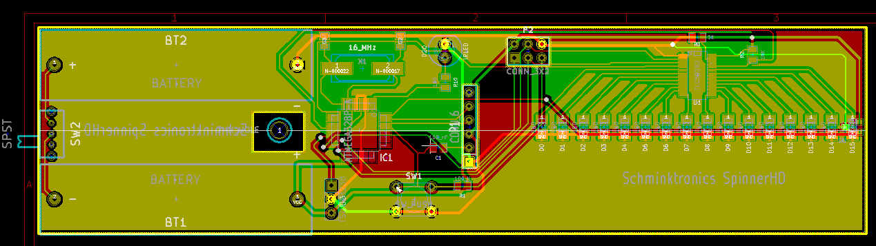
The layout of my first order of SpinnerHD as rendered by OSH Park
And although I was slotted on a panel that was supposed to go to fab on in two days, it apparently filled up right after me and is going to fab today! Hopefully I’ll have the board back in a couple weeks.
Meanwhile, once my order from adafruit arrives, I can do some prototyping with my Arduino. Of course, I should have done this before ordering the boards, but I was impatient and wanted the final thing. I do at least have some experience with a similar chip (the TLC5940) I was able to breadboard, so I think it should all work. But I did order some SSOP breakout boards from adafruit so as soon as I get those, I can verify my design and work on the software before the actual boards arrive. Even if I did do something wrong, I can always rework the PCB and make corrections.
Of course, due to the nature of this device, there’s not an easy way to really see if everything works together on a breadboard anyway. I suppose I could get out an oscilloscope and figure out the amount of time between when the hall effect sensor detects the start of rotation and the time I can turn on the LEDs, but that doesn’t give me any feel for how it actually looks when spinning at 1800 rpm. It also doesn’t tell me if the hall effect sensor gets triggered reliably at the exact same position on each rotation. Only way to figure all that out is to just go for it and see what happens.