Problem discovered

I posted about my problem on reddit yesterday and got a lot of very helpful suggestions. The top voted answer was that switching all those LEDs caused a current transient that shows up in my hall effect line. It probably doesn’t help that I have a long thing Vcc line to the hall effect sensor and that I have a long thin output line from the hall effect sensor running directly under the LEDs and a huge Vcc plane (which is only there due to my poor board design).

I proved this theory by first lifting Vcc from the LED driver, preventing it from pulling current, but keeping everything else the same. This eliminated the problem! Then I realized I didn’t really need to do that–I could have just as well initialized the LED driver to turn all the LEDs off. But finally I realized that probably switching 2 LEDs (turning 1 on and one off) wouldn’t draw too much current, so I soldered Vcc back on and gave that a try:

Hall effect sensor works exactly as expected now with no glitches!

Hall effect sensor works exactly as expected now with no glitches!

Works perfectly, thus providing even more evidence that’s what the problem is.

Now I just need to find a way to get some more caps added on there…

Making (slow) progress

I was able to figure out what’s going on with my hall effect problem last night. I narrowed things down until I discovered that the BLANK line output (pin 8 on Arduino, PB0 on a 328p) is interfering with my hall effect input (pin 2 on Arduino, PD2 on a 328p). The test that proved this was one where I have just this:

void loop() {

digitalWrite(BLANK, HIGH);

digitalWrite(BLANK, LOW);

}

When I look at the hall effect input pin on the scope while holding a magnet near it, I see this:

SpinnerHD-justBlankPulse


I’m not sure why one pulse is much bigger than the rest. Perhaps that’s when the hall effect interrupt gets serviced and interrupts the loop. I just happened to have my trigger point at 1V, so it was triggering on the big pulse.

But, I don’t know WHY this is happening. My meter doesn’t show any continuity between these pins. Looking at the traces, they’re both long, but nowhere close to each other. At the moment, I have no idea what’s going wrong.

Next problem…

Now that the board mostly works, I’ve run into the next problem. The hall effect sensor isn’t working like I expect. I’ve got it on a pullup resistor and expect that it stays high most of the time, then in the presence of a magnetic field, it goes low and stays the whole time. This is exactly how it worked when I prototyped it on an Arduino. But on this board, it pulses while next to a magnet:

SS351-Mistrigger2


Zooming out a little, I can see that it happens almost exactly every 10 ms:

SS361-MisTriggerTiming


It looks like something else is trying to drive that line every 10 ms. But running the exact same code on the Arduino doesn’t do this. And nothing else should be on that line. Maybe it’s a PCB error. Maybe it’s because of the modifications I had to make to fix the board. Maybe I overheated the chip while mounting it. The chip is a little different. I prototyped with the SS451 because it fits in a breadboard. Then I used the SMD SS351AT on my PCB. They really shouldn’t behave that differently though. It also mistriggers when a magnet is not present:

SS351-MisTriggerTiming2

I don’t know what’s going on here. I need to think about this…

While I’m figuring that out, I can do some other tests though. First a quick balance check:

HDSpinnerBalanceTest


The actual balance point is actually a little bit forward from where the hole is drilled, but not by too much. It should still work. My first test alternates each pixel on and off as fast as possible.

Pixel speed test


The main reason I used direct pin outputs for my last spinner is because I was worried sending SPI data wouldn’t be fast enough. But this is extremely impressive! Look at the spacing of those pixels. WOW! Looks like I needn’t have worried! I can’t wait to fix the hall effect problem so I can see what I can do with this! Here’s a closeup for more detail:

IMG_0742

Problem solved!!

After sleeping on it, I suddenly realized what the problem was! Anyone see anything wrong here:

What is wrong in this picture?

What is wrong in this picture?

The on/off switch fit on the board pretty tighly, so I pressed it on there…. but then forgot to solder it in!

Got it soldered in this morning and now it works great! WHEW! Now back to working on the software…

Power problems

Though everything looked good, when I switched to battery power, it stopped working. The test program I’m using lights one LED at a time, switching every 100 ms. So, I can tell that the board runs for between 100ms and 1 second before it just dies. This is similar but much worse than my very first design using batteries that couldn’t supply enough current. However, I’ve used this design with AAA batteries before. I’ve looked at the AAA datasheets and they should be well within spec for this.
But maybe the LED driver is pulling way more current than I thought and dropping the voltage to trip the brownout? I checked with my new bench power supply and I see I can run it down to 2.7 V, so that’s not a problem. At that voltage, it’s only drawing 7 mA of current, so I can’t be pulling too much from the batteries.
Just to be sure, I hooked up a scope and see things like this:
SpinnerHD power problem
Sure enough–after around 200 ms, the power just drops! It wiggles around for a few hundred ms. What can be causing this? There’s no problem with a real power supply… Is it something funky due to the modifications I had to make with the dremel? What is going on?

Assembly!!

I got the plunger and tip for the ZephPaste today. The Zephyrtronics guys were nice enough to modify my order to send me the right things. I wasn’t sure what I needed, so I ordered the pack of assorted tips with a note asking if that was the right thing. They kindly replaced that expensive pack with a 2 pack of tips that worked just fine for me. Thank you Zeph!

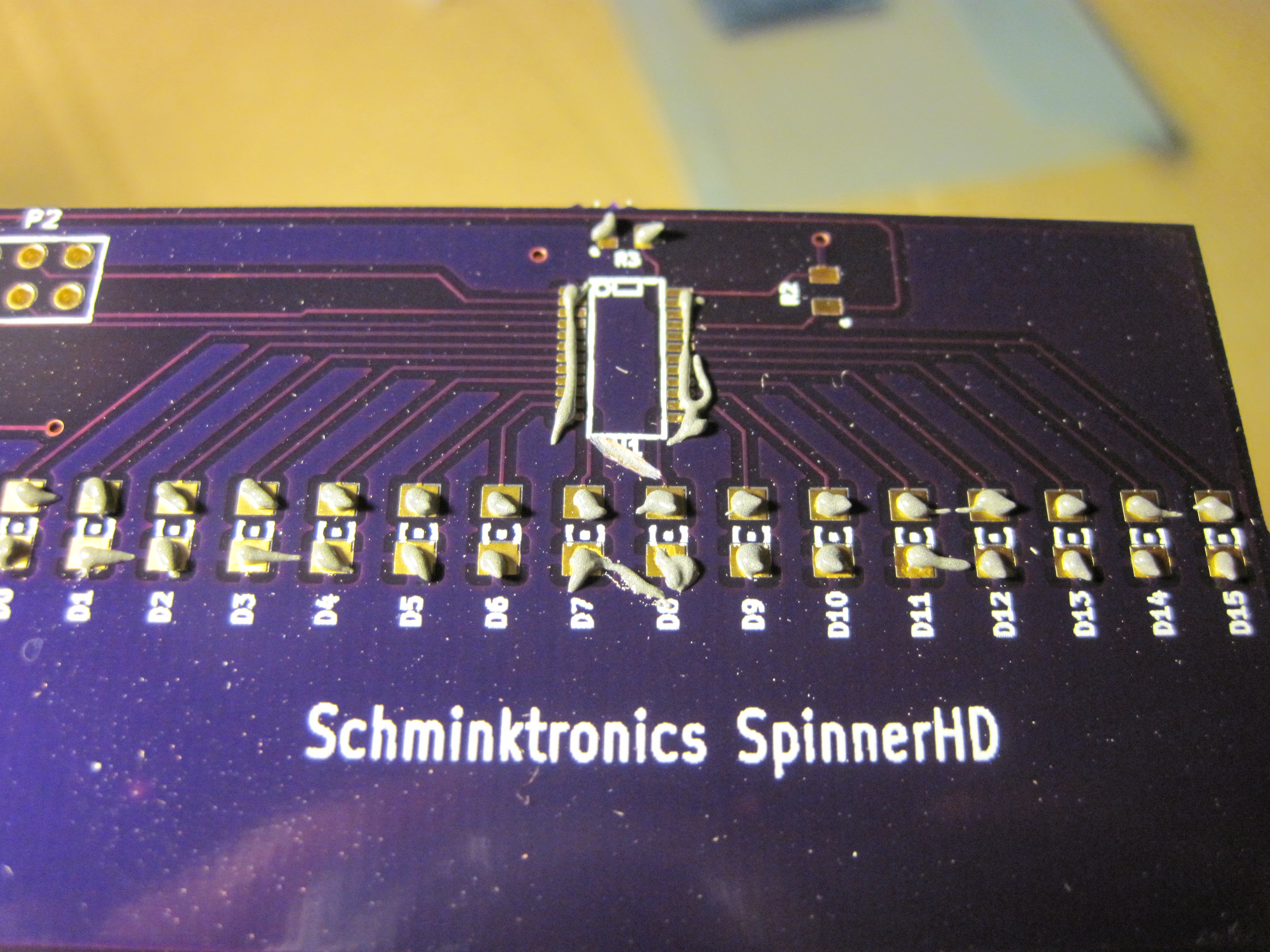
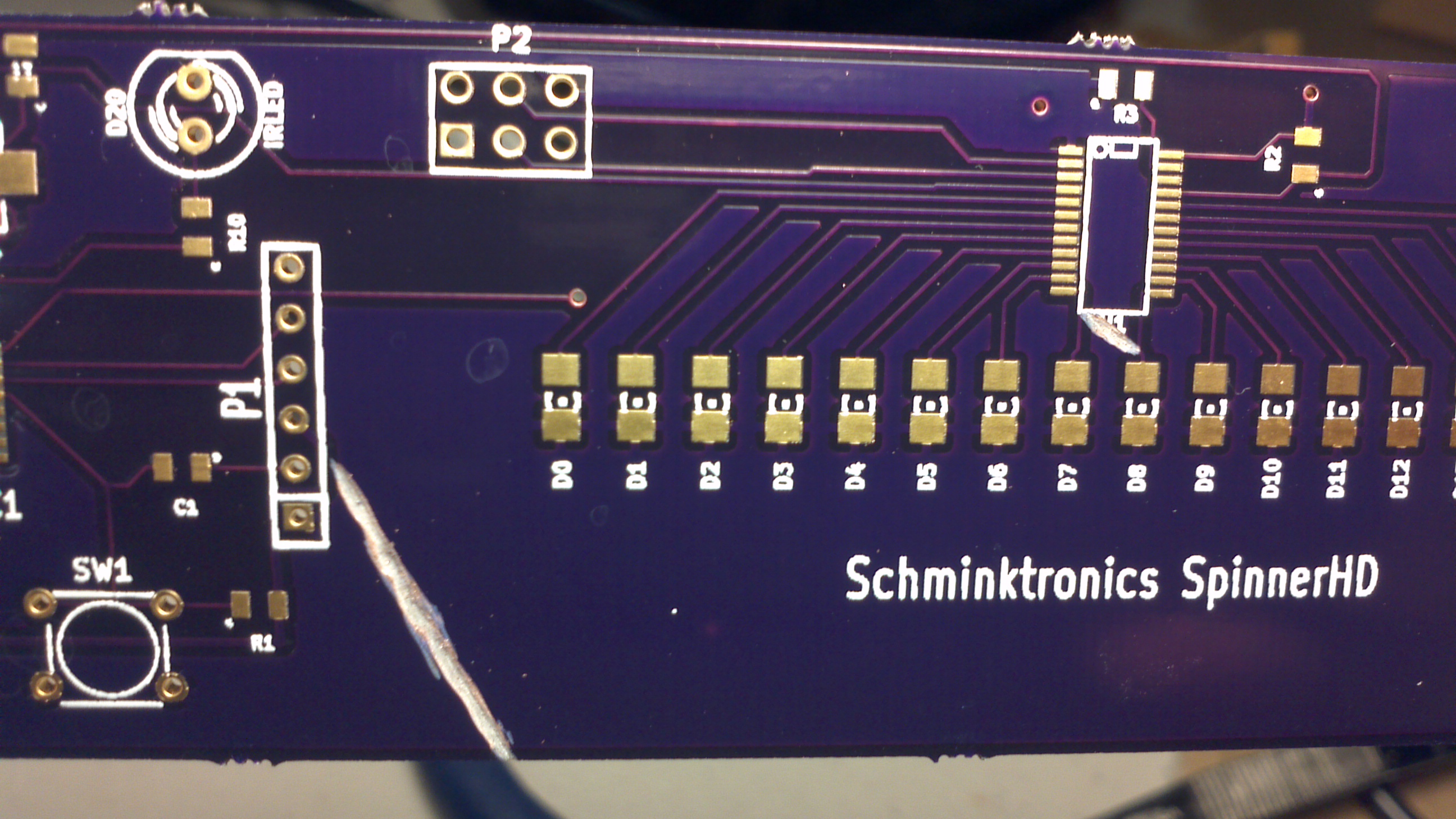
After my day of work, I got to start assembling the board. I started with the LEDs and driver. The driver has the smallest pitch and I didn’t want to solder the LEDs by hand because I thought they’d be hard to align properly. I wasn’t sure how much paste to put on, so I started with this:

Didn't know how much to put, but this is what I started with.

Didn’t know how much to put, but this is what I started with.

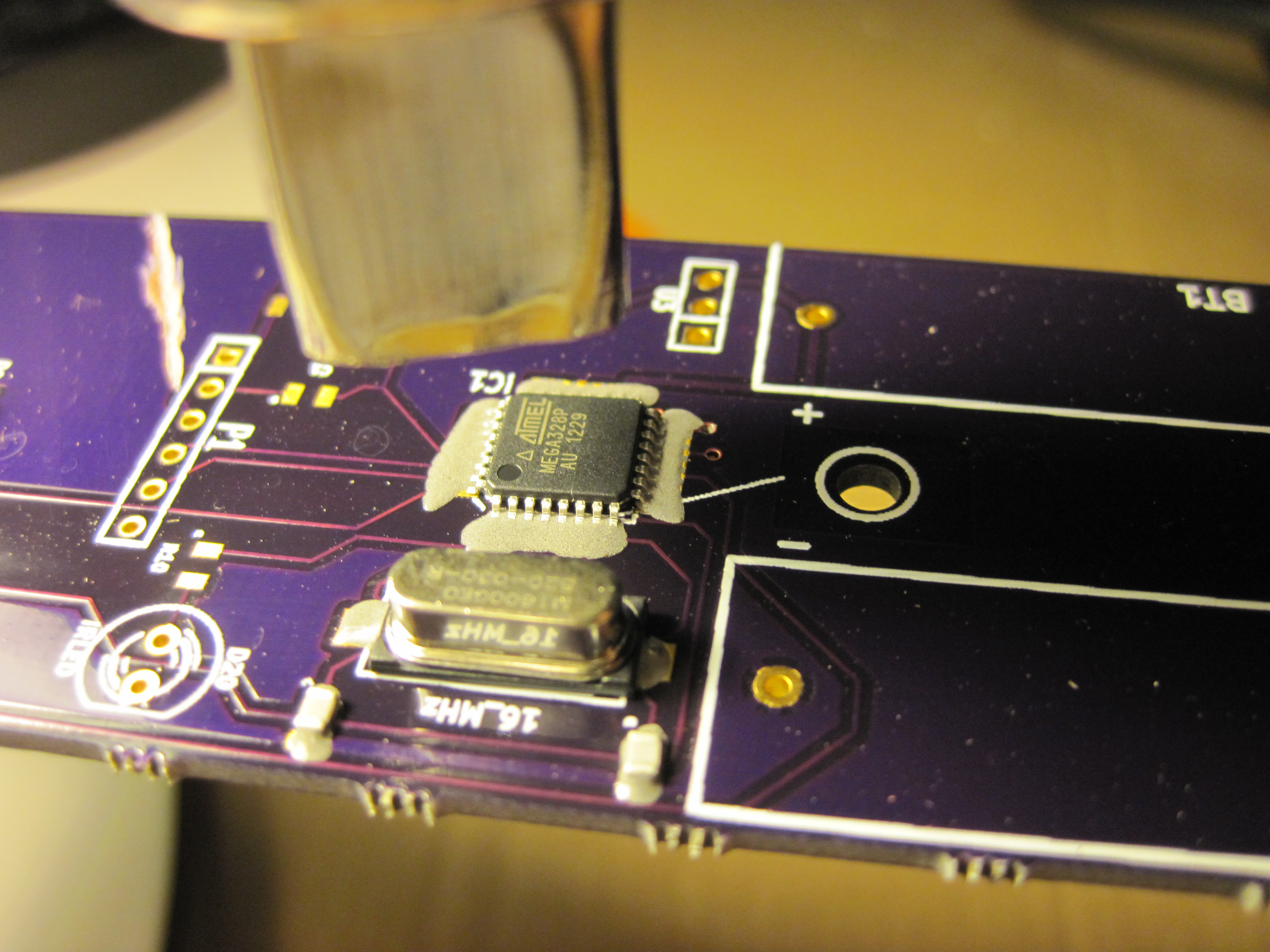
I didn’t really need to be careful about placing the chip as the paste spread around as soon as I set the chip down. I also decided this seemed like a good use for the thermocouple that came with my meter, so I put that on there to monitor the temperature too:

HD Chips

As I heated the paste, it spread out even more, but once it hit the magic temperature, it melted and all sucked back in, aligning the chip to the pads in the process! I did end up with too much solder and ultimately had to wick some away. The heat gun was handy for the alignment though. Then I went down the line heating the LEDS. Those did seem to all align quite nicely, except for one I had to force down with tweezers while the solder was liquid.

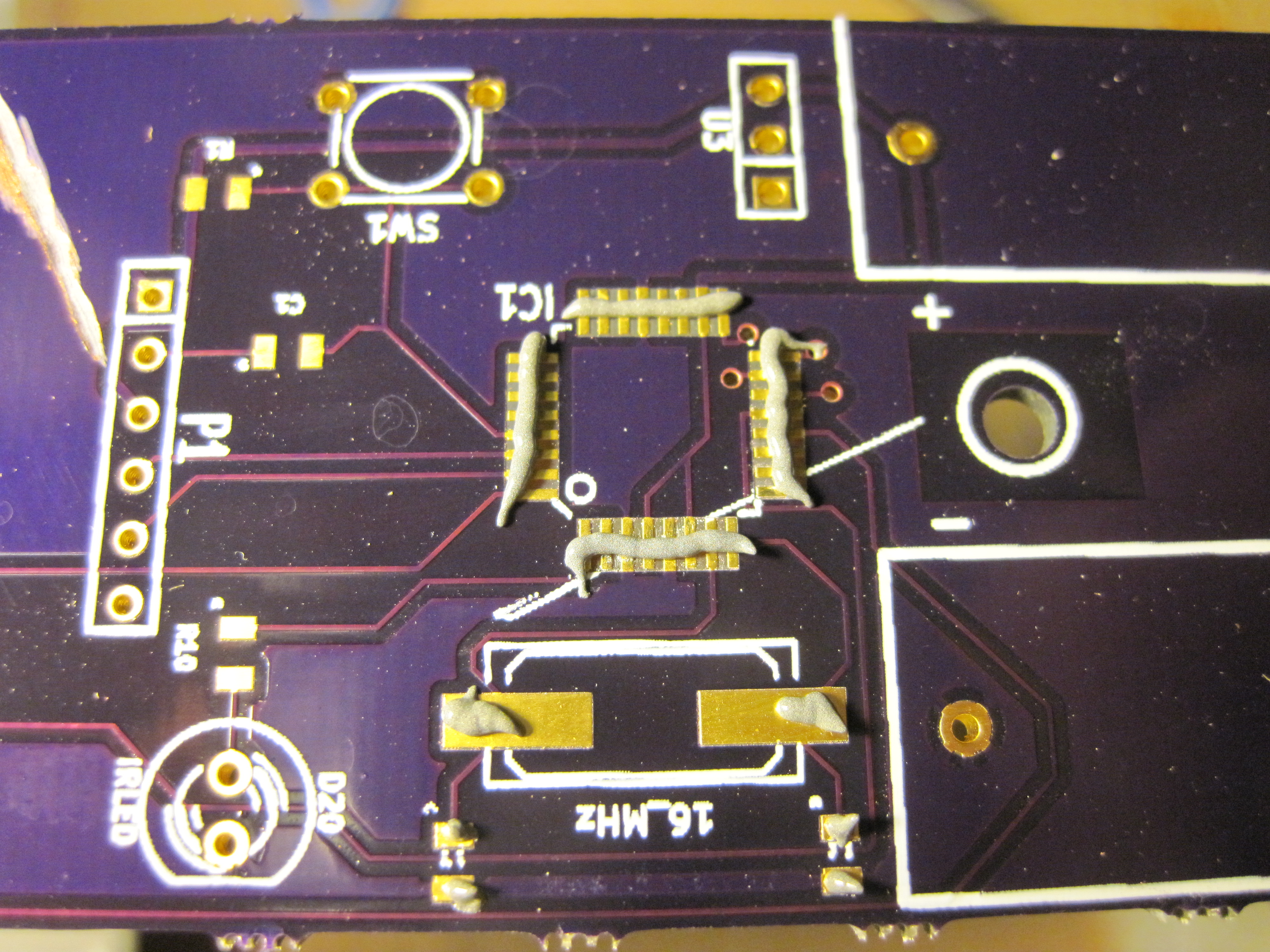
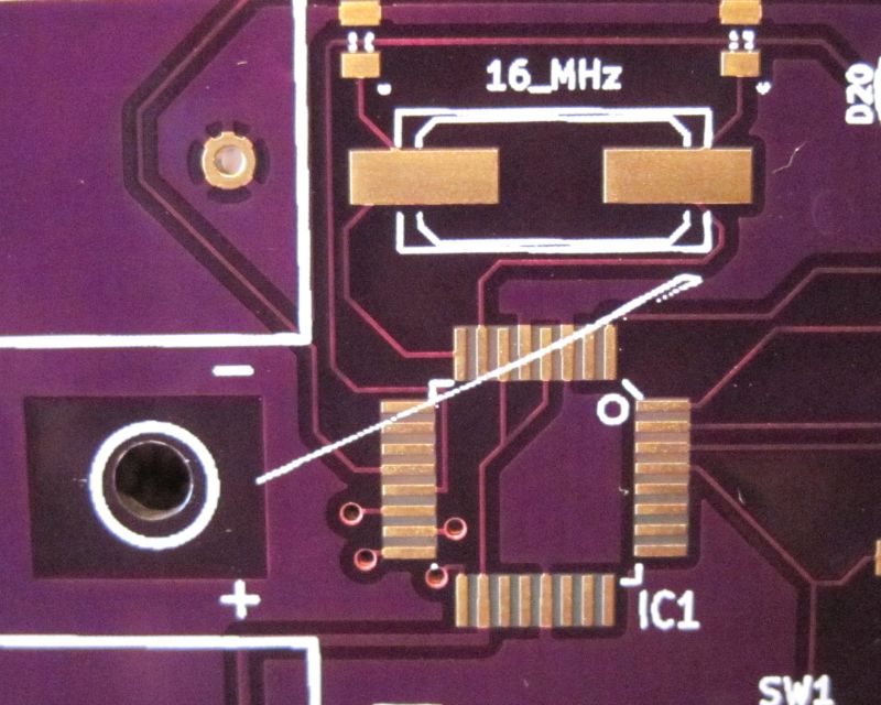
After testing to make sure there were no shorts, I decided to continue on to the processor and crystal:

This is the amount of paste I put on the processor pads

This is the amount of paste I put on the processor pads

Once again, as I heated the paste, it spread out:

Heated paste

But again once it hit the melting point, all the solder sucked onto the pads. But, I did end up with too much solder so I had to wick some away. That looked like too little, so I then applied some more regular solder. I had to do a lot of testing to make sure I had no shorts, then declared it done!

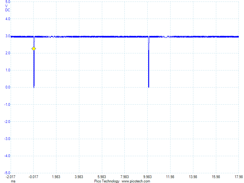
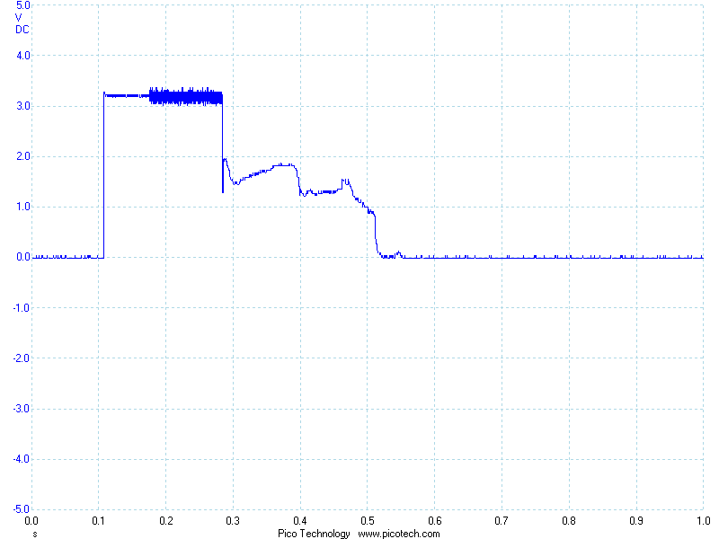
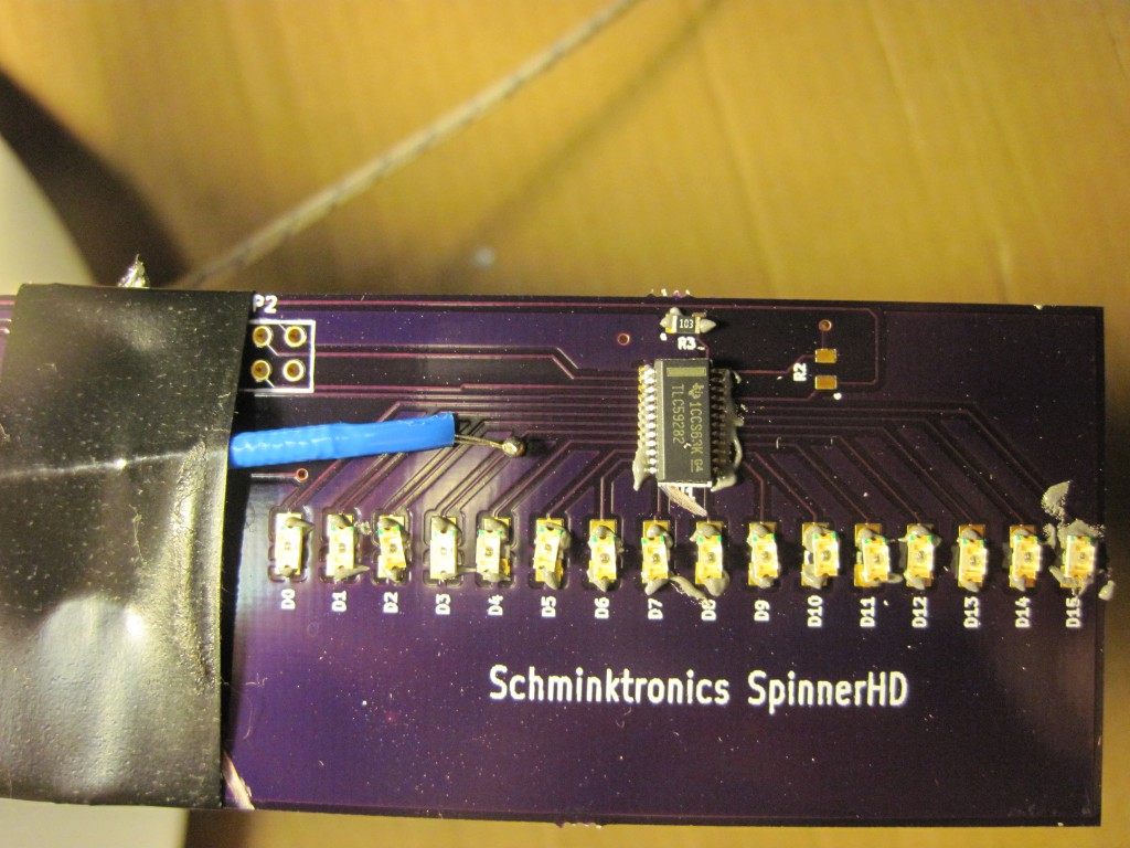
This bare chip doesn’t have the Arduino boot loader, so I had to fire up Atmel Studio to flash that in. BUT, the board didn’t work. I decided to start by checking that the debug header worked. I got lucky and quickly discovered the MISO and MOSI line were shorted. After fixing that, I was able to program the chip. I didn’t have the hex file for the bootloader handy, so instead I just programmed my last test program. Immediately the LEDS lighted up exactly as I had planned. YAY!!

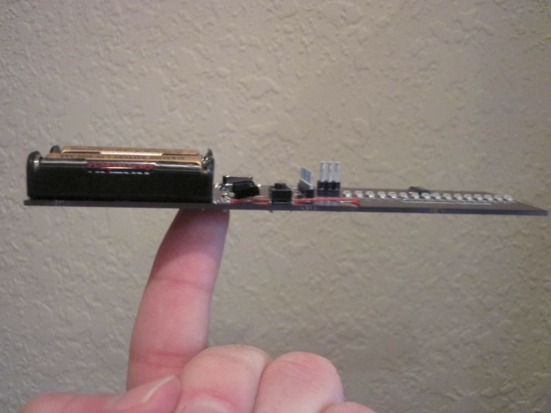
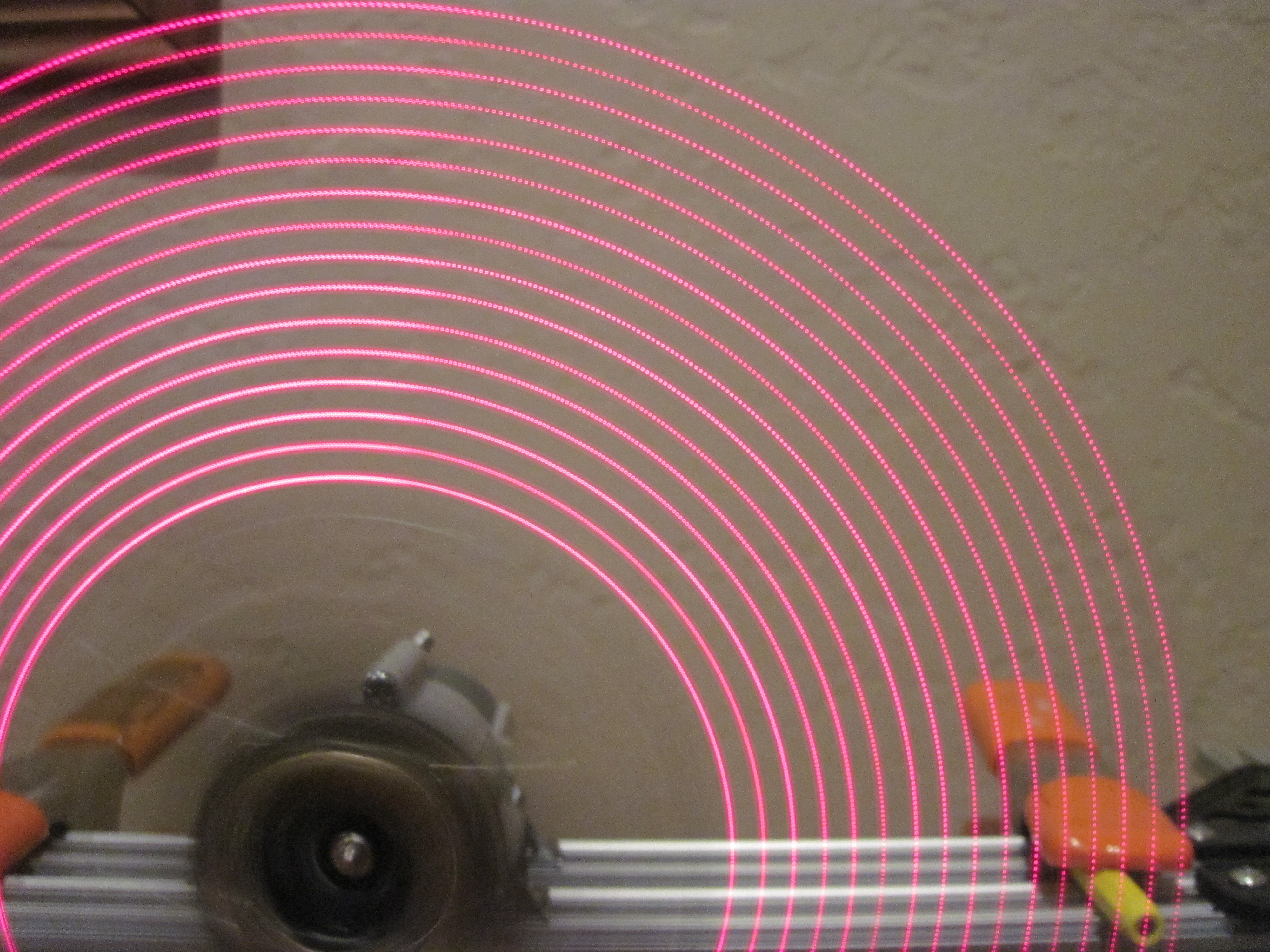
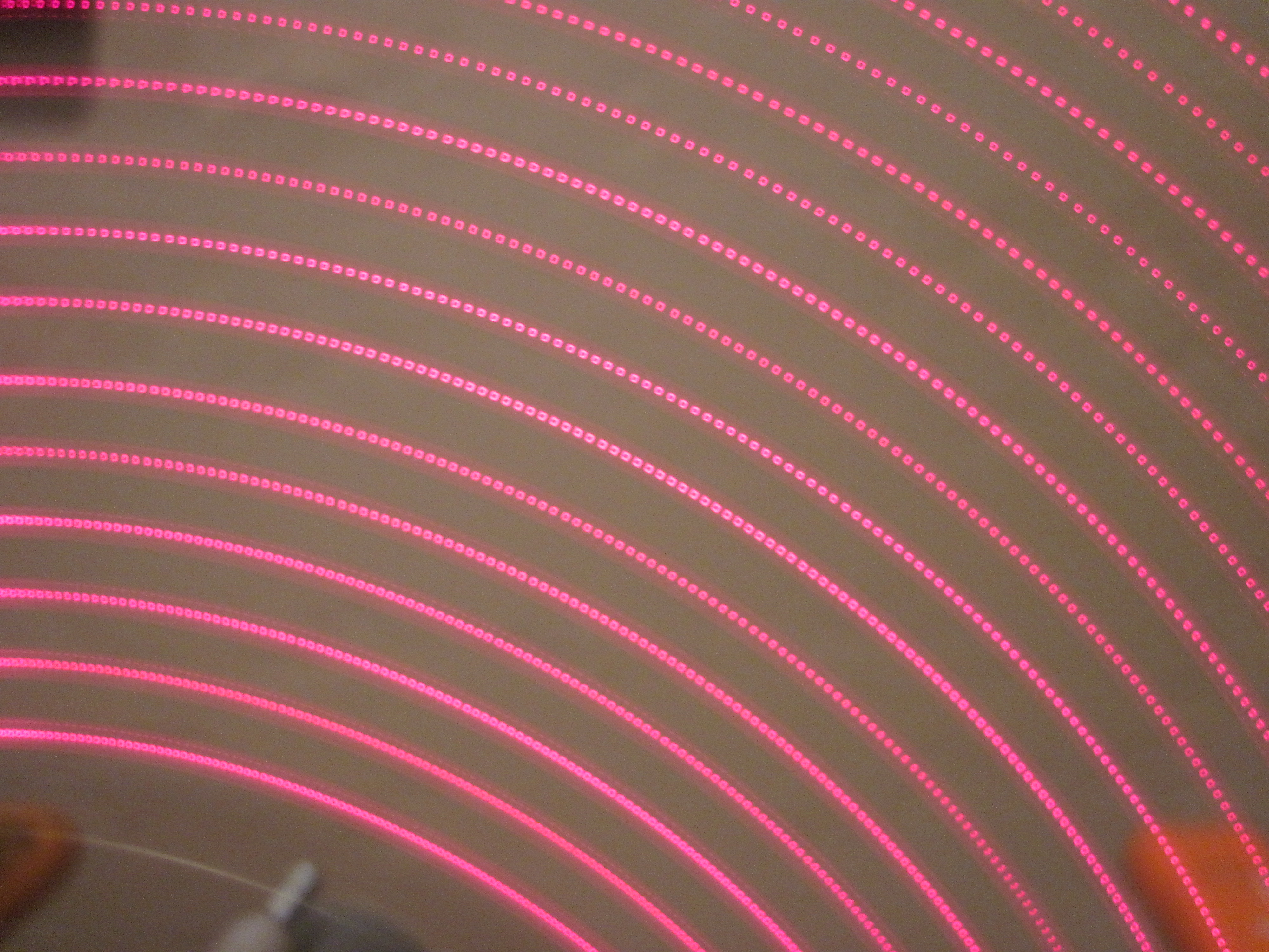
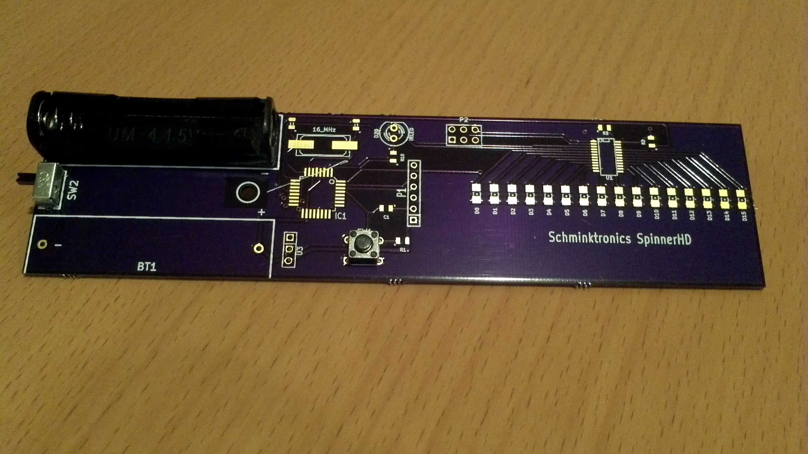
More pics of the finished board and some video later…

Hot air rework station

I’ve stayed away from using solder paste because I thought the paste needed refridgeration, thought I needed to order a custom stencil for each board, and thought I needed an oven or modified hotplate. But, at around the same time, Dave from EEVBlog posted a video on hot to use a hot air gun to do SMD work and CNLohr posted a video showing how he doesn’t use a stencil. I really wasn’t looking forward to soldering all the SMD components on my new board, so I started looking into this option and discovered ZephPaste, which appears to solve the refrigeration problem. So, I figured I’d give this a try!

I first found some cheap hot air guns, but when I read the reviews, I discovered they weren’t only poorly made, they were downright dangerous. With a little more research, I found the X-Tronic 8080, a great rework station that includes a bench power supply, which I really need, and a lighted magnifier, which I really wanted.

XTronic8080


Best of all, it’s made by a company near my hometown! I ordered last week, hoping it would arrive before the weekend. It didn’t, but it did show up today while I still had a partial day off work.

So, I broke out the ZephPaste and got ready to assemble the spinner!

That’s when I finally figured out why I didn’t understand how to use it before. The paste comes in a syringe, but without a plunger or a dispenser tip. I found other things to use as a plunger, but without a tip, it just wasn’t going to work. So, now I had to order more tools with a few day delay. I knew I should have taken a closer look at that paste when I first got it.

Test platform

I got a little more done this weekend. I got my test platform created:

ElectroTestPlatform


You can see here that I ran out of corner pieces. It’s not quite as stable as I’d like, but it’ll do. I also make a trip to Home Depot looking for hardware to be able to make some prototypes. I didn’t find exactly what I wanted, but left with a few potential options. I’ll also take a look at making my own 3D modeled part for testing.

Board modifications

I finally got a chance today to try my planned board modification to fix the design flaw I foolishly put on my board. Just a couple cuts with the dremel to isolate the section of the ground plane that connects the LEDS:

Two cuts to the board and it suddenly becomes useful!

Two cuts to the board and it suddenly becomes useful!

Testing with the continuity checker, it looks like I have managed to remove that section from the ground plane, so now I can instead hook it to Vcc. Not ideal, but it should work. I do have just one more flaw to fix in the board before I can use it. As far as I can tell, this is not my fault, but a manufacturing defect that hit all 3 of my boards exactly the same:

Silkscreen layer got printed on top of my pads!

Silkscreen layer got printed on top of my pads!

For some reason, the silkscreen layer got printed on top of my pads! I looked at my gerbers for the silkscreen and that line isn’t there. It almost looks like the machine just malfunctioned and dribbled out while it moved across the board except that the exact same flaw appears on all three of my boards. Even if it was in my gerbers, the printer is supposed to skip printing anything that crosses a pad. In fact–in the gerbers, there’s a full outline for that chip that didn’t get printed before it went across the pads. Something really went wrong to get it there.

The board might work without me doing anything, but to be safe, I’ve got to clean that off before I spend time trying to securely solder the processor on there. Hopefully that peels off easily…


The boards have arrived!!

12 days after I ordered, and the boards are here!!!!

First order of boards back from OSH Park!

First order of boards back from the manufacturer!

Thank you OSH Park!! Of course, I do have to make some modifications before these are ready for use. After looking at the board layout, I did figure out a relatively easy way to fix my wiring problem, but it does involve a dremel and some fairly small traces to cut. We’ll see how well that works. But, if nothing else, I can use these first boards to make sure that  all my through hole parts fit as I expect:

Making sure all the parts fit as I expect on the professionally drilled board

Making sure all the parts fit as I expect on the professionally drilled board

Everything looks great! The new reset switch I got from adafruit fits, the on/off switch fits, and the battery holder fits! I can’t wait to see if my dremel skills are good enough to fix up this board…