Board layout

Now with the schematic done and all the component mapping done, it’s time to work on the board layout. In my experience with this project, this is an iterative part that takes a lot of time. Laying out a board for most projects may be easier, but for this, I had several restrictions that made it even more challenging.

First, due to the function of the board, I had to place all the LEDs in a very specific place. With this version of the board, I have the same restriction, but it will hopefully be less of a problem since the LEDs are hooked to the LED driver instead of the processor and the pin layout for the LED driver looks like it will make the routing much easier.

Second, since I’m spinning the board at a fairly high speed (1,800 rpm to update the display 30 times per second), I also need to plan where the center of balance is and make sure I can drill a hole there with enough clearance that it doesn’t touch anything else. This ends up being fairly critical and part of the iterative nature of this project. The previous version of this project has 2 AAA batteries on one end of the board with the center of balance near the end of the batteries that’s towards the center. If I switch to a LiPo battery, that center changes. I could instead use a single battery, but would have to rotate it to be parallel to the short side of the board (currently 2″ x 6″ or hopefully 1″ x 6″) so that it could still be spun around without being off balance. That could let me reduce the length of the board, so production costs would be smaller. But that also might require me to go back to adding a DC-DC converter, which I don’t want to deal with right now though. I could put the two AAA batteries directly in the middle of the board, but that means that the LEDs wouldn’t be as far away from the center of rotation. But, it does give me the option of putting LEDs on both sides of the board and spinning the board at half the speed. Or I could shift the LEDs on one side just a little to double the apparently DPI.

For now though, I’ll go back to my tried and true method of both batteries on one side of the board parallel to the long edge of the board. It looks like I won’t be able to shrink the width down to 1″ to save $30 from OSH Park, but it does mean that I’ll get the board done sooner.

Spinner restart

The last time I worked on my spinner project was in October when I finally got my first working version. I then made big plans for the next version:

  • Switch to an ATmega32u4 so I could switch to using USB to program it instead of serial.
  • Add a DC-DC converter so I can be more flexible with my power options, like using a single 1.5V battery to power this. I also wanted to do this just to practice with making a DC-DC converter.
  • Add the option to power it with a LiPo battery and include a LiPo charging circuit, mainly to practice and learn how to do this.
  • Switch to using a constant current LED driver to simplify the circuit and layout and be able to support more LEDs.
  • Use a professional board printing service to get experience with that and because it makes my board layout easier and should greatly reduce the number of manufacturing errors I have to test for and deal with.
  • Fix all the problems I found in my previous version.

After 3 months of putting it off, I realized part of my problem in getting started was that I was trying to do too much. (To be fair, another large part of the problem was the holidays of course.) So, I cut my list back to just three things:

  • Switch to the constant current LED driver (TLC59282) to get more LEDs (thus the name of the project–SpinnerHD)
  • Use a professional board printing service (OSH Park)
  • Fix all the problems I found in my previous version

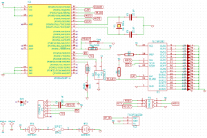
Since it’s been 3 months, I had to remember some of the decisions I made (my previous board had some post build modifications that weren’t reflected in the schematic). But, after a couple of hours, I managed to finish the schematic for my new project:

First version of the schematic for SpinnerHD

First version of the schematic for SpinnerHD

Okay, I realize it’s pretty ugly. If you have any suggestions on a better way to do things, please let me know!

BTW: I wish KiCad had a PDF export for the schematics because I don’t have a PDF export printer installed on this computer yet, so the png version will have to do. Or, you can download an archive of the current state of the project here: SpinnerHD-Take1 I don’t know if that includes everything you need for the project or not. One of the other reasons the schematic took so long is because it was created on another computer and I had problems getting all the libraries and modules over to this one. I didn’t notice the archive option until I wrote this post, so I hope it works.