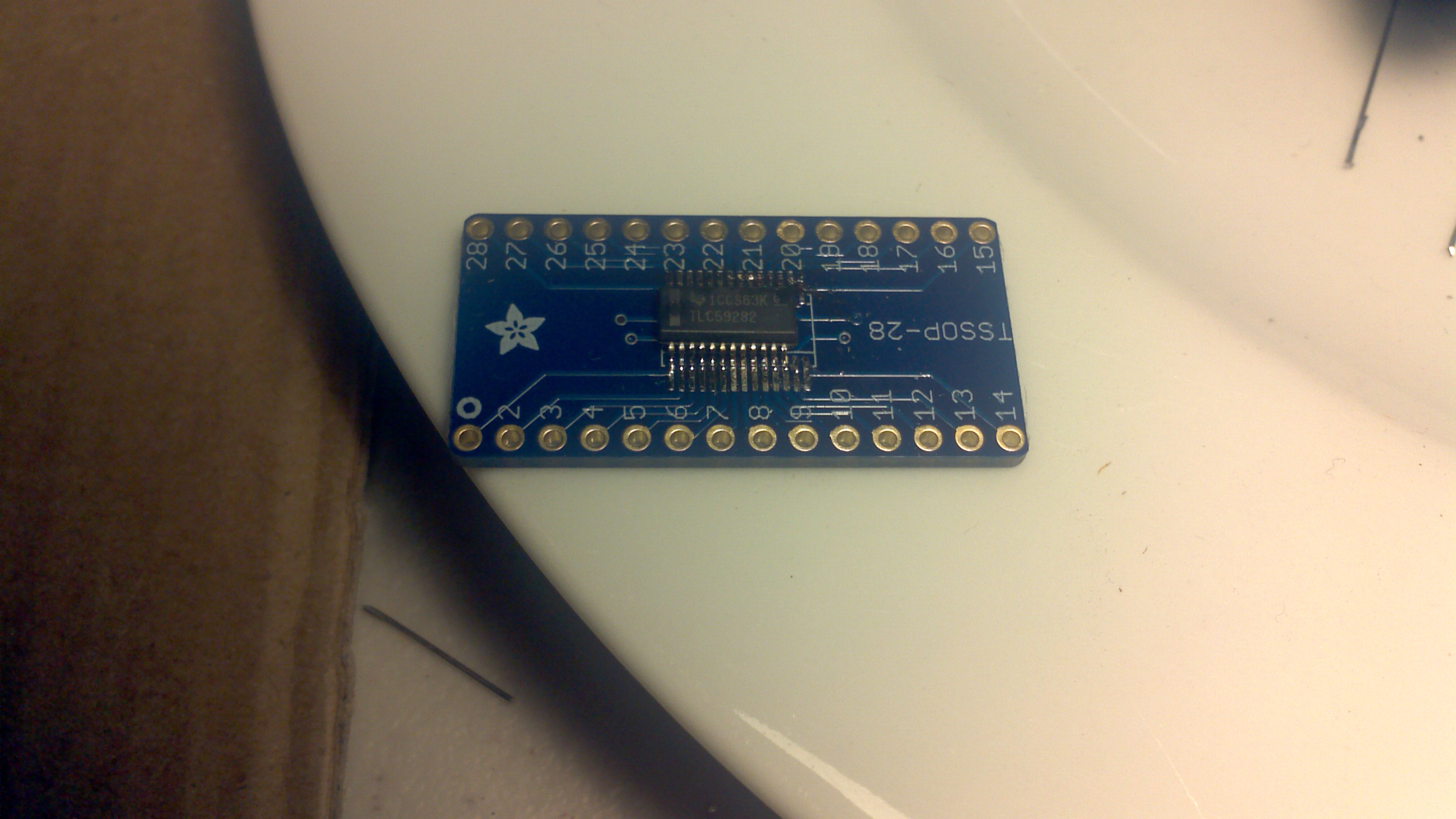
Now that I have the working breakout board for the TLC59282, I was able to get the software working and get it tested pretty quickly. I did have one minor wiring problem that was just due to the way I’ve got my breadboard setup, but after I fixed that, everything worked as I expected. This chip is WAY easier to use than the TLC5940!
In the process of setting up the SPI, I did discover another problem with the boards I had ordered. Turns out the Slave Select line is on the same pin as my IR in for the remote control, but in order for SPI to work correctly, this pin needs to be kept low. So, in order to move the pin, I first looked at my board layout to see if I could move it to a pin closer to the IR and make the layout easier. I read a post (on reddit I think) where someone said they do the planned PCB layout first, before the schematic, so they have a better idea of how to hook things up to make the layout easier. I should have done that, or at least looked for some optimizations, but it’s no big deal. I’ll remember to do that next time as I was able to find some trivial changes to the circuit that made the layout easy. The schematic now looks like this:
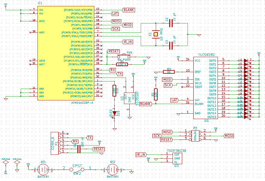
New schematic based on changes I discovered while prototyping on the Arduino
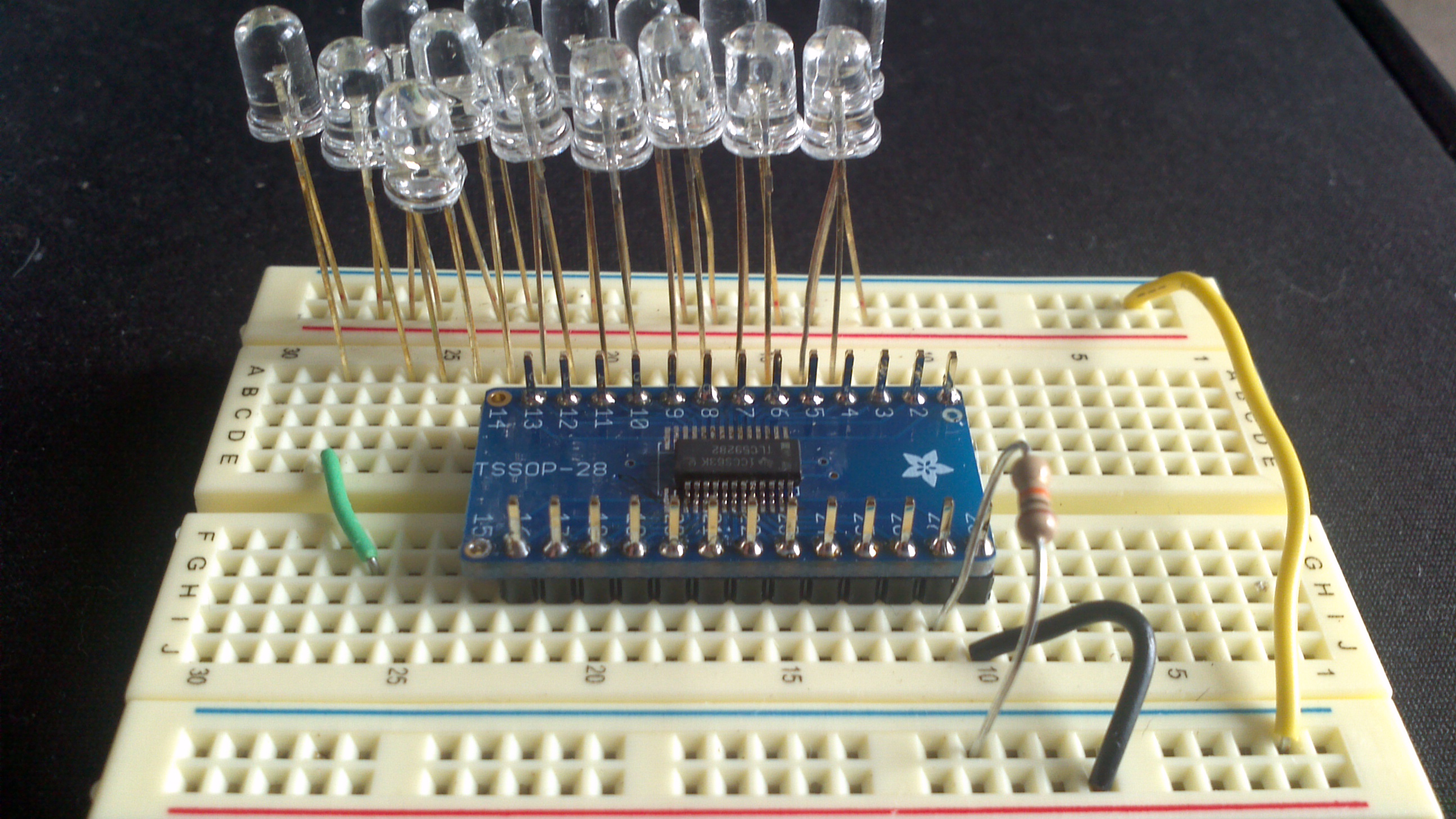
I did get everything prototyped out, including the LED controller, hall effect sensor, and IR input. I verified they all worked together, the hall effect sensor worked on the new interrupt pin (which I’m hoping works better than a PCINT I was using on the previous version), and the IR works with everything else running. I also did a bunch of speed tests. I’m able to run the SPI at 8 MHz and wanted to see if that was fast enough to keep up with the spinning board. From the tests I’ve done, it looks like it will be more than enough!
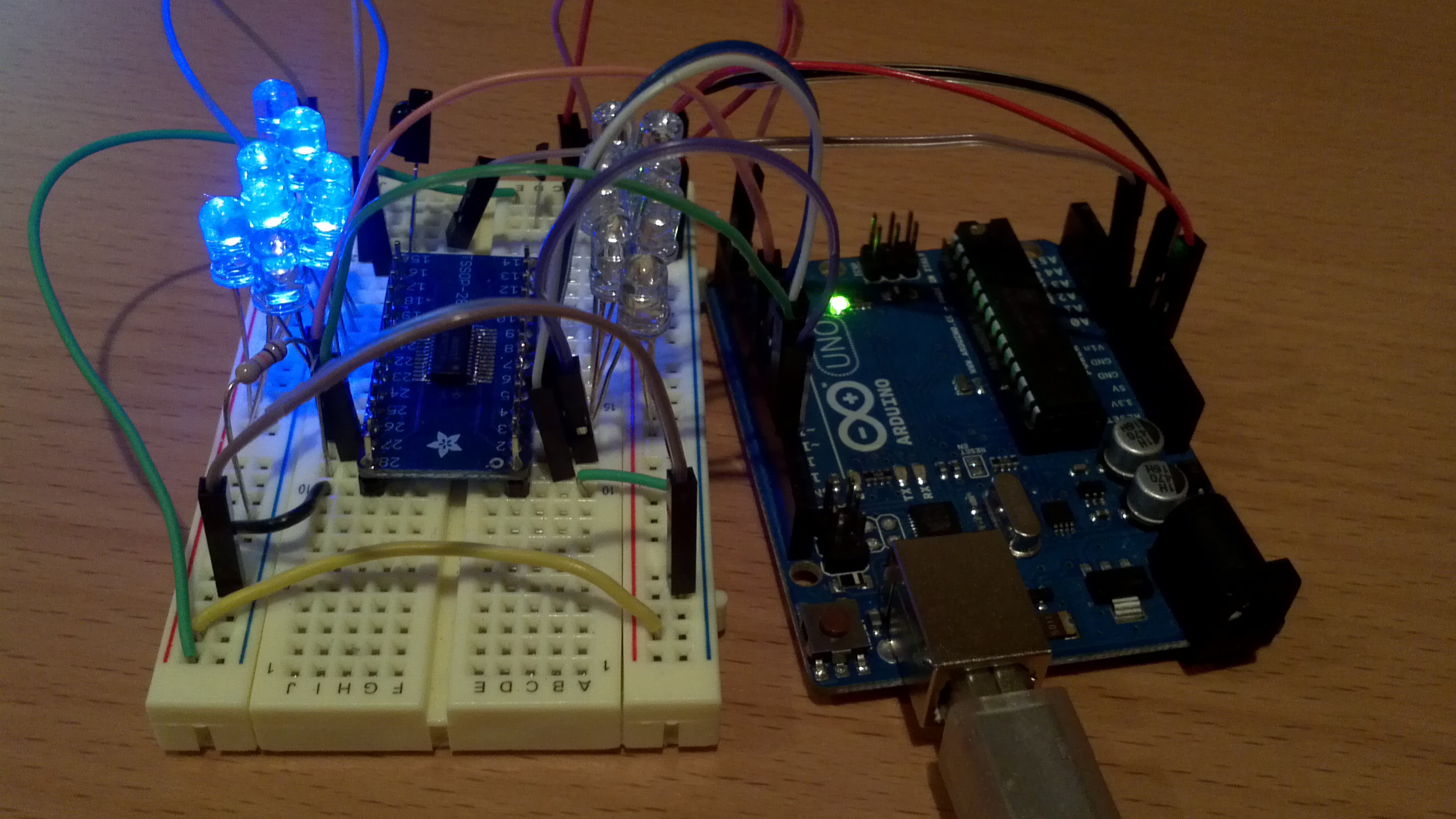
Breadboarded version of the SpinnerHD to test the TLC59282 and make sure everything works like I expect.
And here’s the code I used to test the prototype.