Hot air rework station

I’ve stayed away from using solder paste because I thought the paste needed refridgeration, thought I needed to order a custom stencil for each board, and thought I needed an oven or modified hotplate. But, at around the same time, Dave from EEVBlog posted a video on hot to use a hot air gun to do SMD work and CNLohr posted a video showing how he doesn’t use a stencil. I really wasn’t looking forward to soldering all the SMD components on my new board, so I started looking into this option and discovered ZephPaste, which appears to solve the refrigeration problem. So, I figured I’d give this a try!

I first found some cheap hot air guns, but when I read the reviews, I discovered they weren’t only poorly made, they were downright dangerous. With a little more research, I found the X-Tronic 8080, a great rework station that includes a bench power supply, which I really need, and a lighted magnifier, which I really wanted.

XTronic8080


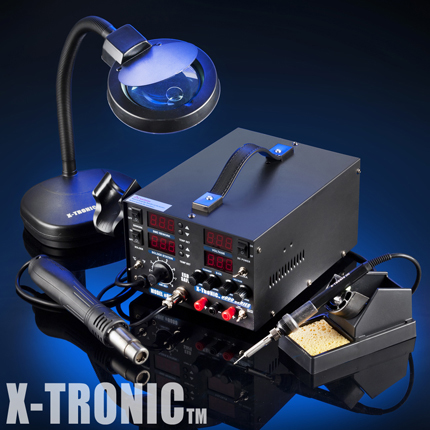
Best of all, it’s made by a company near my hometown! I ordered last week, hoping it would arrive before the weekend. It didn’t, but it did show up today while I still had a partial day off work.

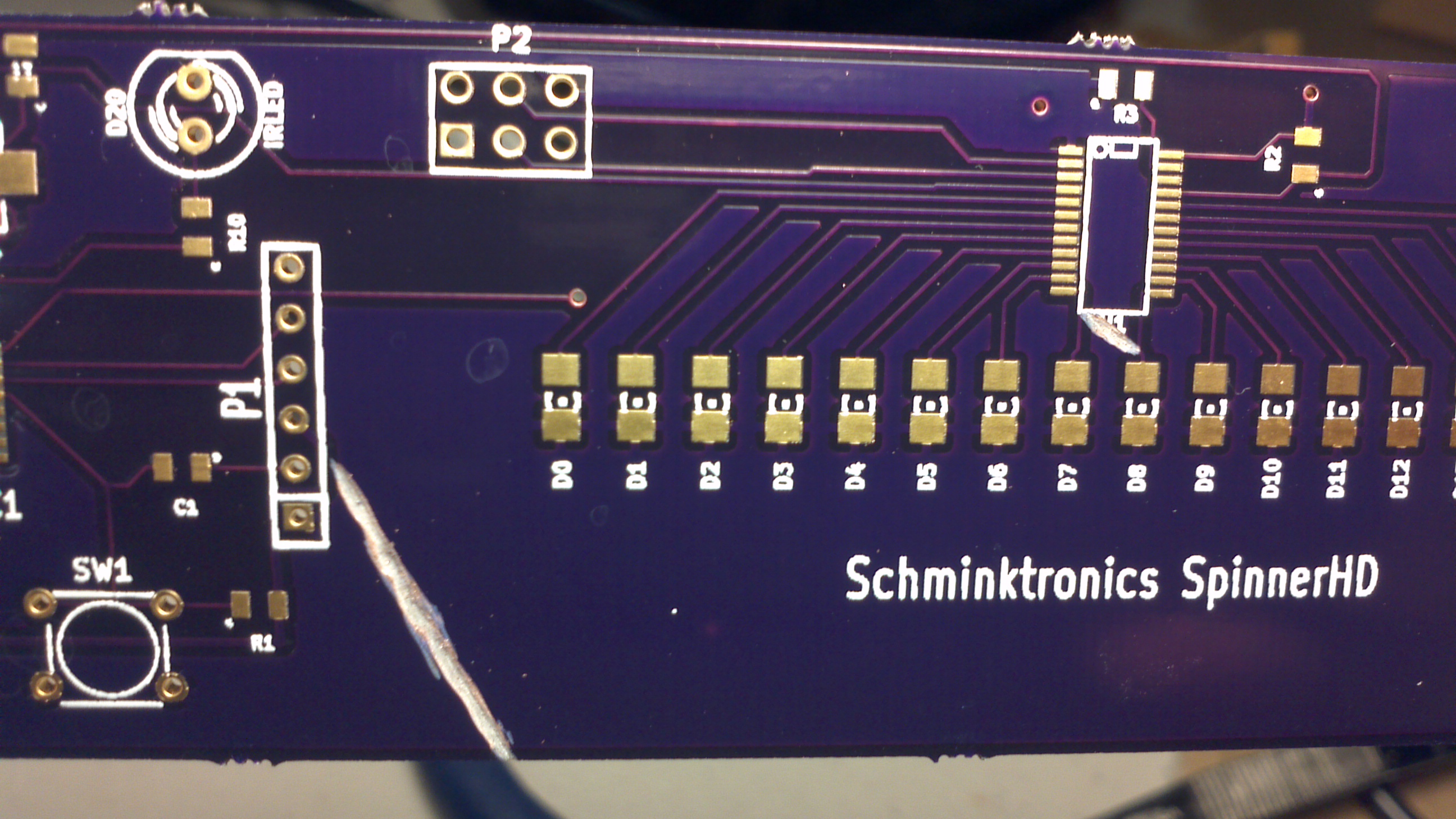
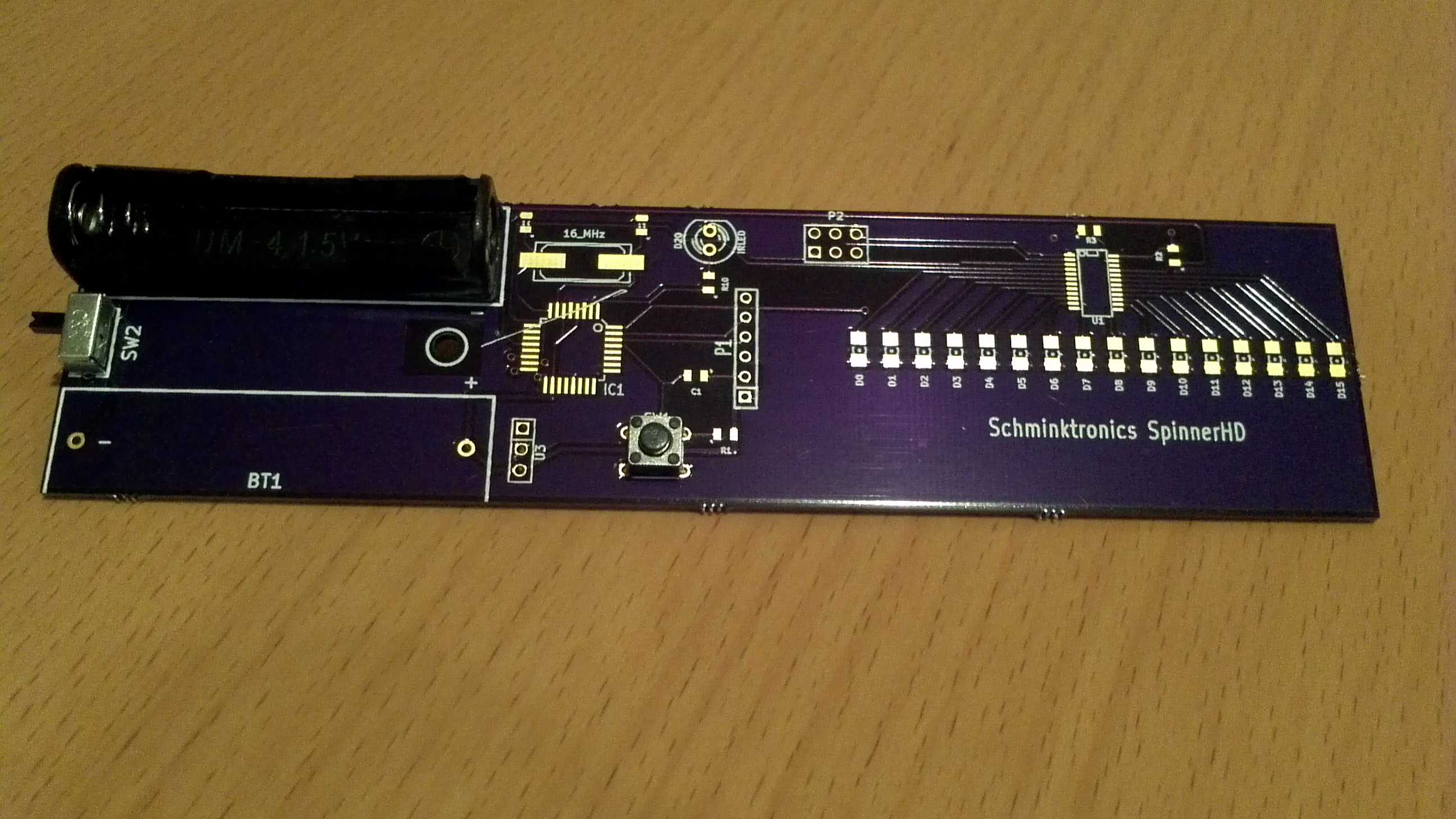
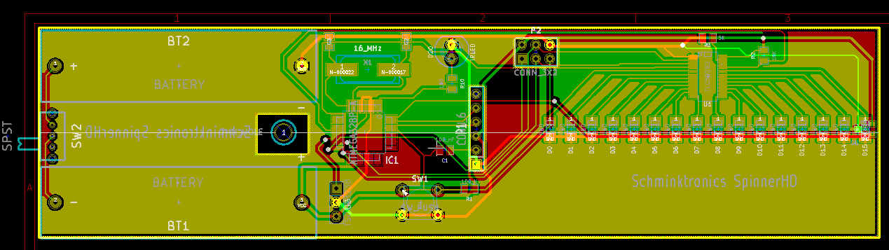
So, I broke out the ZephPaste and got ready to assemble the spinner!

That’s when I finally figured out why I didn’t understand how to use it before. The paste comes in a syringe, but without a plunger or a dispenser tip. I found other things to use as a plunger, but without a tip, it just wasn’t going to work. So, now I had to order more tools with a few day delay. I knew I should have taken a closer look at that paste when I first got it.

Test platform

I got a little more done this weekend. I got my test platform created:

ElectroTestPlatform


You can see here that I ran out of corner pieces. It’s not quite as stable as I’d like, but it’ll do. I also make a trip to Home Depot looking for hardware to be able to make some prototypes. I didn’t find exactly what I wanted, but left with a few potential options. I’ll also take a look at making my own 3D modeled part for testing.

Board modifications

I finally got a chance today to try my planned board modification to fix the design flaw I foolishly put on my board. Just a couple cuts with the dremel to isolate the section of the ground plane that connects the LEDS:

Two cuts to the board and it suddenly becomes useful!

Two cuts to the board and it suddenly becomes useful!

Testing with the continuity checker, it looks like I have managed to remove that section from the ground plane, so now I can instead hook it to Vcc. Not ideal, but it should work. I do have just one more flaw to fix in the board before I can use it. As far as I can tell, this is not my fault, but a manufacturing defect that hit all 3 of my boards exactly the same:

Silkscreen layer got printed on top of my pads!

Silkscreen layer got printed on top of my pads!

For some reason, the silkscreen layer got printed on top of my pads! I looked at my gerbers for the silkscreen and that line isn’t there. It almost looks like the machine just malfunctioned and dribbled out while it moved across the board except that the exact same flaw appears on all three of my boards. Even if it was in my gerbers, the printer is supposed to skip printing anything that crosses a pad. In fact–in the gerbers, there’s a full outline for that chip that didn’t get printed before it went across the pads. Something really went wrong to get it there.

The board might work without me doing anything, but to be safe, I’ve got to clean that off before I spend time trying to securely solder the processor on there. Hopefully that peels off easily…


The boards have arrived!!

12 days after I ordered, and the boards are here!!!!

First order of boards back from OSH Park!

First order of boards back from the manufacturer!

Thank you OSH Park!! Of course, I do have to make some modifications before these are ready for use. After looking at the board layout, I did figure out a relatively easy way to fix my wiring problem, but it does involve a dremel and some fairly small traces to cut. We’ll see how well that works. But, if nothing else, I can use these first boards to make sure that  all my through hole parts fit as I expect:

Making sure all the parts fit as I expect on the professionally drilled board

Making sure all the parts fit as I expect on the professionally drilled board

Everything looks great! The new reset switch I got from adafruit fits, the on/off switch fits, and the battery holder fits! I can’t wait to see if my dremel skills are good enough to fix up this board…

Prototyping and software testing

Now that I have the working breakout board for the TLC59282, I was able to get the software working and get it tested pretty quickly. I did have one minor wiring problem that was just due to the way I’ve got my breadboard setup, but after I fixed that, everything worked as I expected. This chip is WAY easier to use than the TLC5940!

In the process of setting up the SPI, I did discover another problem with the boards I had ordered. Turns out the Slave Select line is on the same pin as my IR in for the remote control, but in order for SPI to work correctly, this pin needs to be kept low. So, in order to move the pin, I first looked at my board layout to see if I could move it to a pin closer to the IR and make the layout easier. I read a post (on reddit I think) where someone said they do the planned PCB layout first, before the schematic, so they have a better idea of how to hook things up to make the layout easier. I should have done that, or at least looked for some optimizations, but it’s no big deal. I’ll remember to do that next time as I was able to find some trivial changes to the circuit that made the layout easy. The schematic now looks like this:

New schematic based on changes I discovered while prototyping on the Arduino

New schematic based on changes I discovered while prototyping on the Arduino

I did get everything prototyped out, including the LED controller, hall effect sensor, and IR input. I verified they all worked together, the hall effect sensor worked on the new interrupt pin (which I’m hoping works better than a PCINT I was using on the previous version), and the IR works with everything else running. I also did a bunch of speed tests. I’m able to run the SPI at 8 MHz and wanted to see if that was fast enough to keep up with the spinning board. From the tests I’ve done, it looks like it will be more than enough!

Breadboarded version of the SpinnerHD to test the TLC59282 and make sure everything works like I expect.

Breadboarded version of the SpinnerHD to test the TLC59282 and make sure everything works like I expect.

And here’s the code I used to test the prototype.

Exciting and not so exciting day

Last night a little after 7 pm, I got email from OSH Park that my boards were back from fab and by 9:30, email that my boards had been shipped! Fantastic news since I am hoping to get them before President’s Day so I can populate them on my day off work.

On Thursday, I got the headers I needed to use the breakout boards for the TLC59282. This morning, I finally got a chance to put them on. As it turns out, the headers I ordered aren’t quite what I wanted–they are double sided, so the pins are the same length on each side. They will still work though and were quick and easy to get soldered on:

My breakout board mounted on a breadboard

My breakout board mounted on a breadboard

So finally I can get to prototyping and working on the software. I used the same breadboard I had when using the TLC5940 earlier because it already had a bunch of LEDs on it. Everything was good up until the point where I realized the LEDs were hooked between the chip and VCC, not the chip and GND. Took a quick look at the datasheet and then at my schematic and realized I did wrong. In my schematic, I have the common side all to GND, not VCC. At first I thought I could work around this by cutting the traces to GND and fix them to go to VCC. Then I remembered that I did a GND fill, so I don’t have just one or two traces to cut total and one new wire to VCC, but three traces for each LED and adding new wire hacks (grr–why can’t I remember the real name of these wires right now?) to each LED.

So, in other words, the boards are pretty much DOA. They aren’t completely useless. I’ll still get to use them to test the balance, make sure all the drill holes and everything else was manufactured as expected, and photograph to use as the banner for this blog. I did actually expect that this first board probably would have issues that would make it not work. I was expecting those problems to be manufacturing issues I didn’t know about though, and not my own stupid errors. As I mentioned in a previous entry, I did know I was risking this by ordering the boards by prototyping, but it’s still disappointing.

Now this post does make it sound like I’m pretty rash and impulsive, making many mistakes. Can’t argue with you there. I knew the risks though and it’s not that big of a deal–just another week or two delay. This time I’ll get everything prototyped before I order the next board.

Home Depot

I love Home Depot. It’s great for all my projects. I’ve spend a lot of time lately trying to find a simple toggle switch that can handle up to 5 Amps. I finally found one I liked that’s about $6 a piece and was about to order some, but held off. Then I stopped by Home Depot just to get some PVC to wind an electromagnet around. I figured I’d look through the electronics isle just in case they had a switch. Suddenly, inspiration struck! A cheap switch that can handle at least 5 A? A light switch of course–for only 69 cents!!:

Cheap lightswitch I found at Home Depot that looks like it will meet my needs and pretty cheaply

Cheap lightswitch I found at Home Depot that looks like it will meet my needs and pretty cheaply

Okay, it does say 15A 120 VAC only, but I assume that will also work fine with <12 VDC @ 5 A. I did also pick up a 1/2″ PVC pipe so I could start on my first electromagnet.

My goal was to use 26 AWG wire, 13 turns per layer (to make a coil 1/4″ long) and 10 layers. As it turns out, winding these is rather difficult, especially without a form. I tried to wind it close to the edge of the pipe so I could see if a 1/2″ ball bearing could be picked up by it, but I couldn’t get enough tape on the edge to keep everything from falling apart. So, I decided to wind it further up the pipe so I could use a lot more tape. Without any side pieces to hold the shape, it’s difficult to get each layer of wires to stack on the previous. But I did eventually get approximately 5 layers done:

My first attempt at winding an electromagnet

My first attempt at winding an electromagnet

Figure that’s good enough for now, so I’ll see what it can do. I did a quick test with the meter to find about 1.8 Ohm resistance. Since that’s not going to limit the current much, I didn’t want to try it with a real power supply and instead started with a 9V battery. I got some sparks off it, so I went for a magnetic test. Placed my ball bearing close to it and did see it move! Not far or far, but it did move. I tried putting the ball bearing inside the PVC, as my current goal is to hold it in there. That test failed though. I couldn’t get the ball in the right position at the same time as keeping the the power on to the coil. And, of course, one problem with a PVC pipe is that it’s not transparent, so I can’t see what’s going on inside. One of my next goals is to find something I can see inside of for this… I wish I had been able to wind the coil closer to the end of the pipe so I could try sucking the ball bearing into it. Maybe after I work on my winding technique, I can try that again later.

Missing parts…

The breakout boards I ordered from adafruit arrived today. As soon as I could, I soldered on a TLC29282 so I could breadboard it and start testing it and writing the software for the spinner. Turns out it is kinda difficult to solder at this pitch. Although, I don’t think my soldering iron is working very well either. I accidentally left it on for several days one time and now it feels a little different. As I was testing that I hadn’t left any solder bridges, it suddenly occurred to me that I didn’t have any of the headers I needed to actually use this:

2013-02-04_21-37-20_889


So, now it’s a couple more days while I wait for headers to show up in the mail… 🙁

Board ordered!

I forgot to mention last night that I finally found the type of reset button I wanted from adafruit and got that ordered. I had a terrible time trying to find these on digikey, but after I got the part number from adafruit, I was able to find them on there. In the end, ordering from adafruit is way cheaper though. These are about 53 cents each from digikey (in the small quantities I wanted), but this pack of 20 from adafruit comes out to 12.5 cents each!

I did notice one design error that came up after I adjusted the footprint for the reset switch to match the one I found. Then I made a few other minor changes and got my board submitted!!

The layout of my first order of SpinnerHD as rendered by OSH Park

The layout of my first order of SpinnerHD as rendered by OSH Park

And although I was slotted on a panel that was supposed to go to fab on in two days, it apparently filled up right after me and is going to fab today! Hopefully I’ll have the board back in a couple weeks.

Meanwhile, once my order from adafruit arrives, I can do some prototyping with my Arduino. Of course, I should have done this before ordering the boards, but I was impatient and wanted the final thing. I do at least have some experience with a similar chip (the TLC5940) I was able to breadboard, so I think it should all work. But I did order some SSOP breakout boards from adafruit so as soon as I get those, I can verify my design and work on the software before the actual boards arrive. Even if I did do something wrong, I can always rework the PCB and make corrections.

Of course, due to the nature of this device, there’s not an easy way to really see if everything works together on a breadboard anyway. I suppose I could get out an oscilloscope and figure out the amount of time between when the hall effect sensor detects the start of rotation and the time I can turn on the LEDs, but that doesn’t give me any feel for how it actually looks when spinning at 1800 rpm. It also doesn’t tell me if the hall effect sensor gets triggered reliably at the exact same position on each rotation. Only way to figure all that out is to just go for it and see what happens.

Layout complete?

After a couple more hours over the past two nights, I think my layout is complete. I have one more thing to verify–need to make sure the pad layout is correct for the TLC29282, but other than that, I think I’m ready. SSOP-24 looks REALLY small. I don’t think I’d have any chance of getting that etched properly with my home etching technique. I only hope OSH Park can etch that small!

I’m also nervous about having them drill the center hole since the center of balance may be off from where I’ve predicted. This is the same center I used on my previous board, so I have some experience that suggests it’s correct, but it could be off. Then again, they’ll do a much better job of drilling this in the right place than I will. What’s the worst that can happen? It’ll be off balance a little?

This is the layout I consider "almost final". I need to go over it just a little more, but I think this is close!

This is the layout I consider “almost final”. I need to go over it just a little more, but I think this is close!