More discoveries

I figured that even if the hall effect sensor glitches when switching a bunch of LEDs in the presence of a magnetic field, I could still make use of this board by not switching anything while the hall effect sensor is active. So I changed the code to display a binary pattern. When the hall effect interrupt is triggered, hold the current LED display for 1 ms to give the board time to spin past the magnet, then reset the pattern to 0.

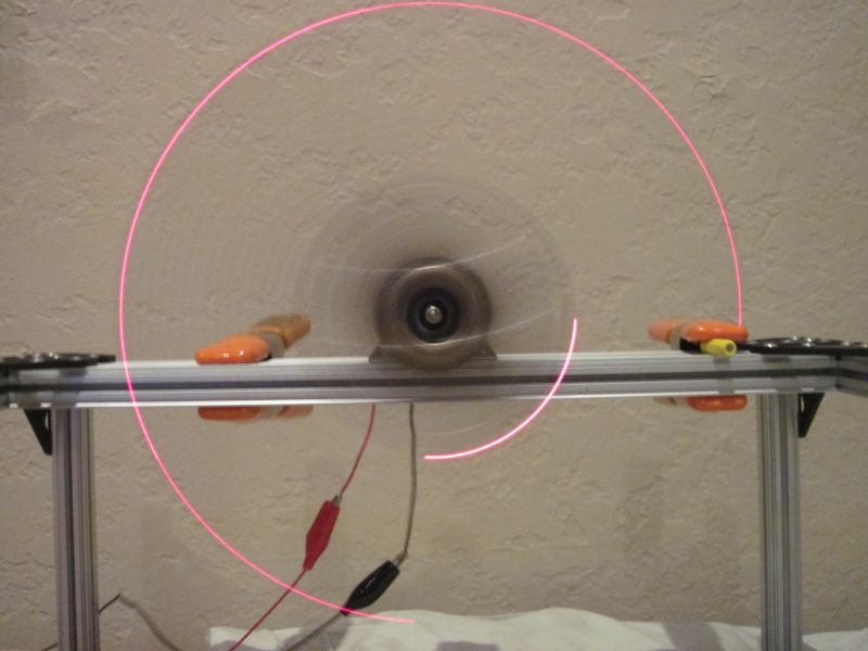
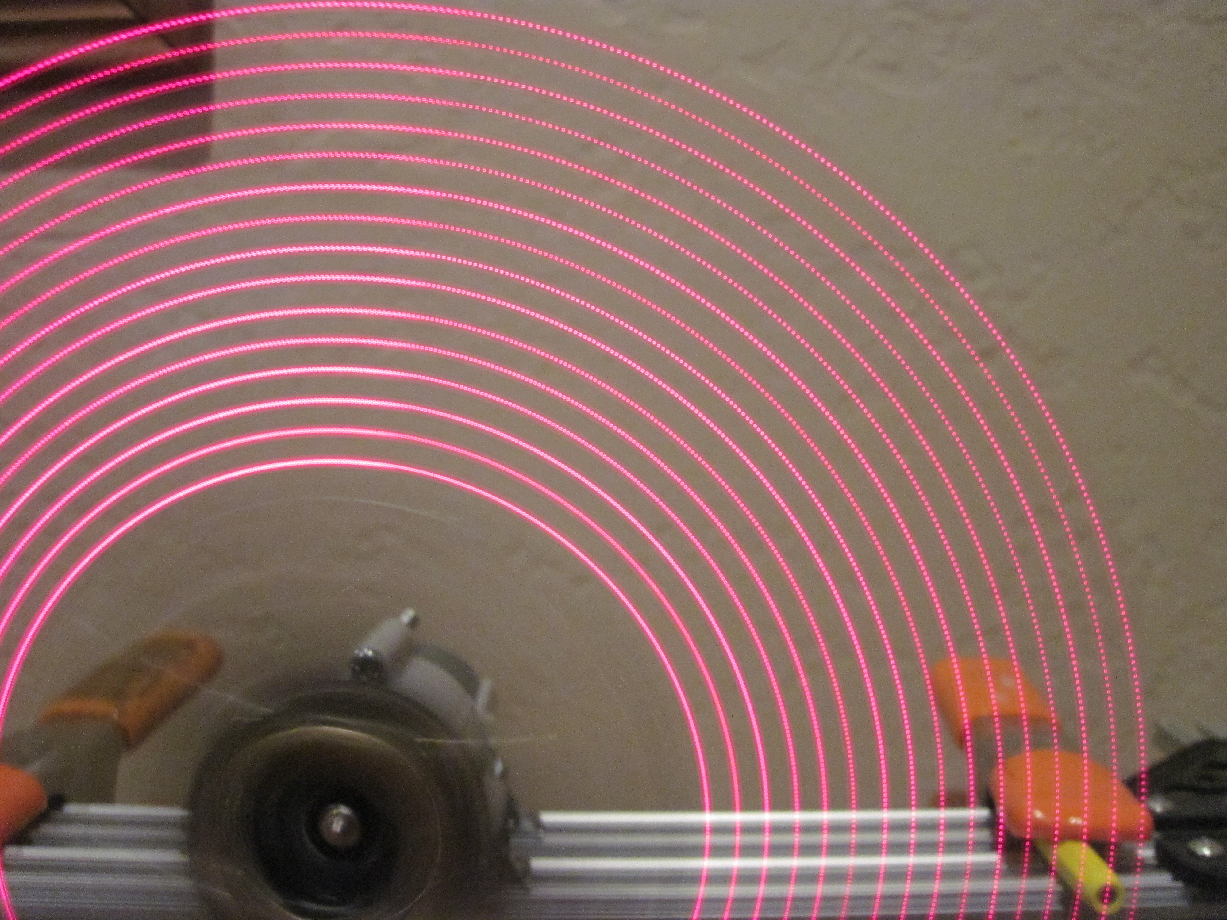
As soon as I turned on the board, I could tell there was a problem. No more than 6 LEDs ever lit up, even with no magnet to reset the pattern. But, all the LEDs that were flashing were going too fast to clearly see what was happening so I spun it around to see what it looked like:

Binary Pattern Glitch

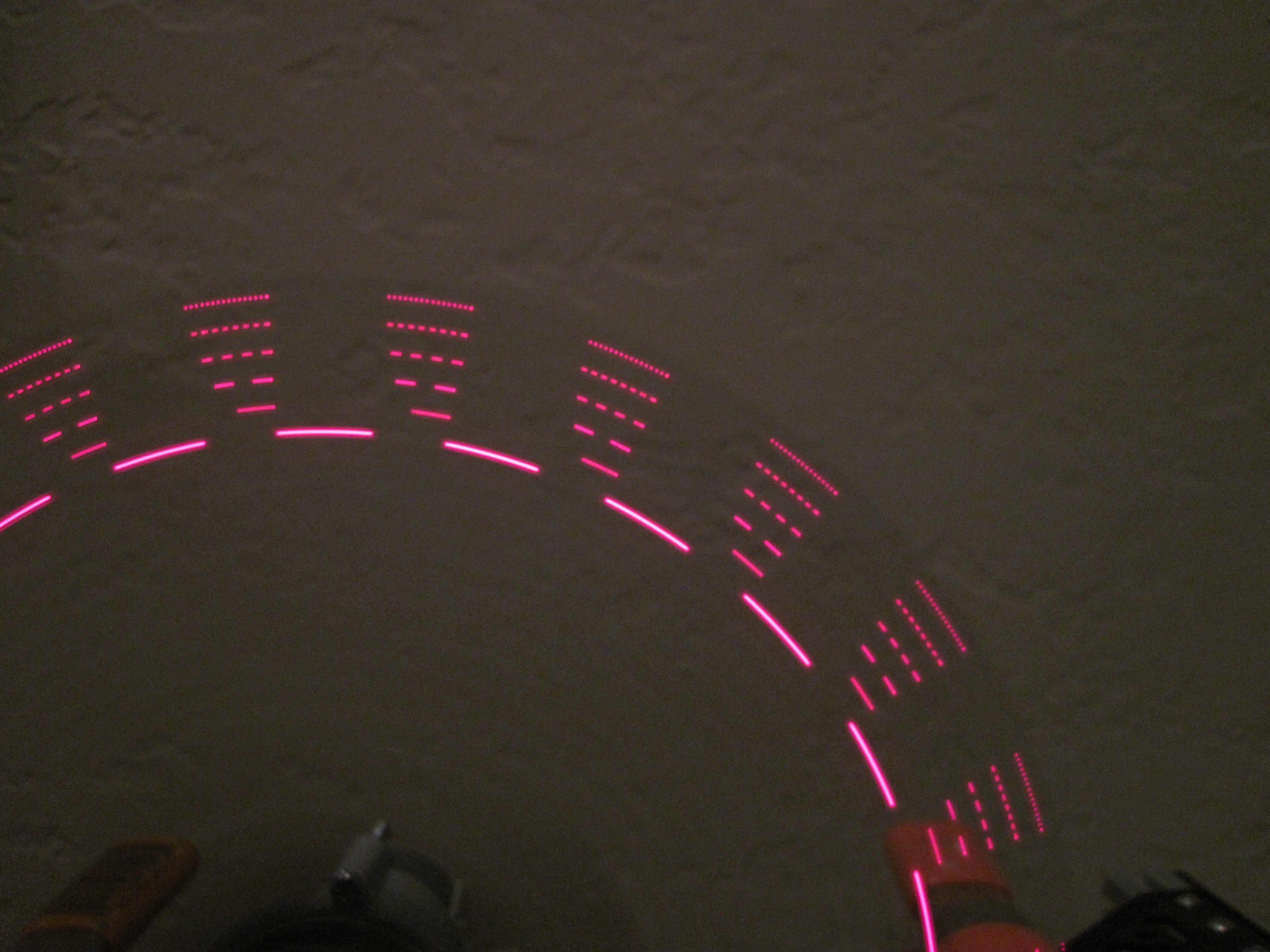
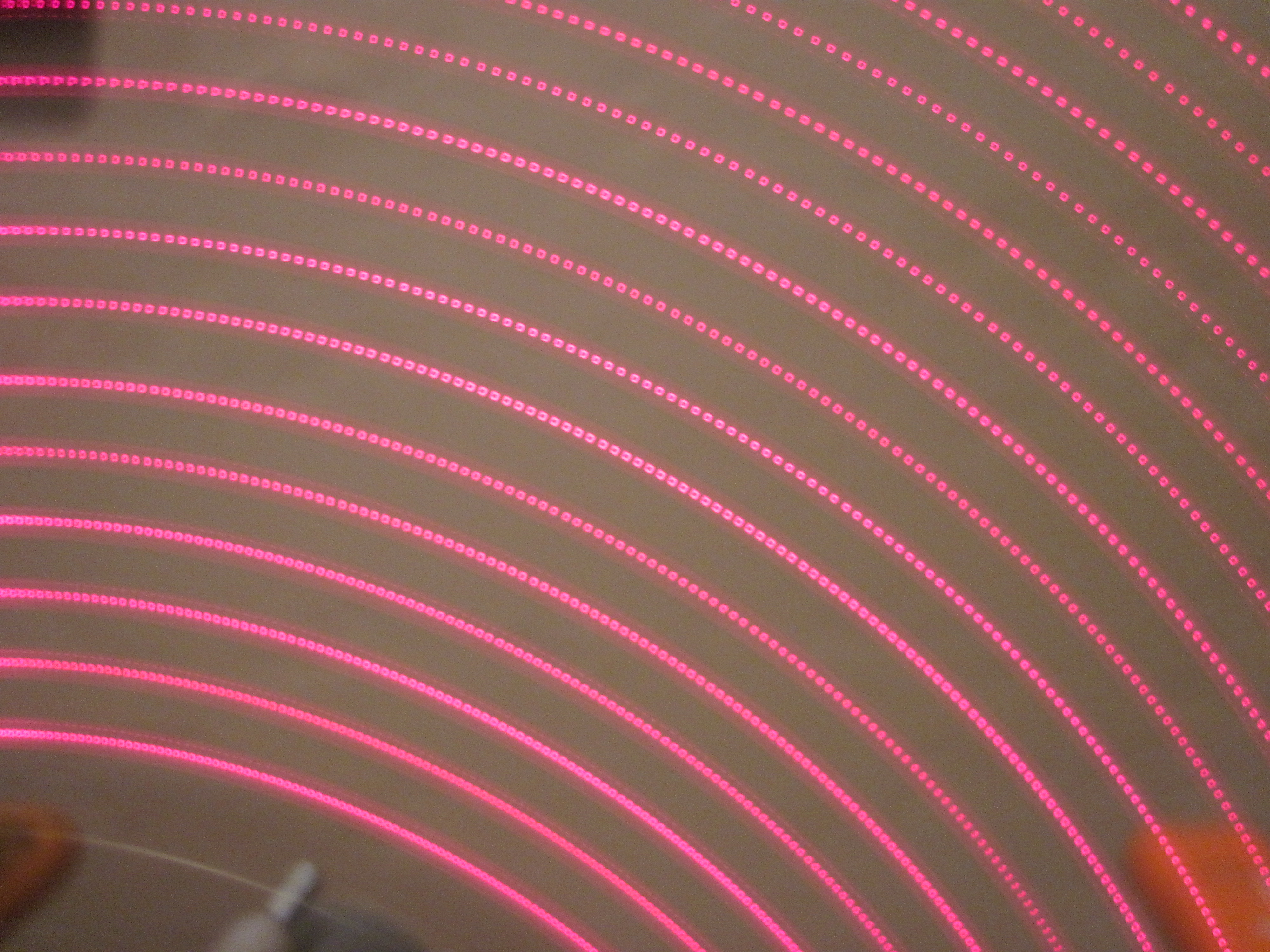
Once again, I am impressed by how fast I can switch the LEDs and how small they appear when I do. (Look at the outer most LED–you may have to view the full size image to even see the individual pixels.)

But from this, I can see what’s happening. Each time I have 5 LEDs on, then switch them all off (and in this case, switch one more on), I get a false hall effect pulse. This is seen in the pictures by the single LED holding for 1 ms, then resetting back to the beginning of the pattern.

So, I can’t really do anything interesting with the board until I fix this problem with the current. My first attempt at putting on some filter caps failed, so I need to find a better way to do it or work on another board design that has the filter caps included in the layout.


Temporary test plan

I figured I really should test all this before spending a ton of money on it, so I walked around Home Depot and found a tube with a 1/4″ outside diameter. The only magnetic thing I could find to fit inside was a #16 nail, so I bought some of those.

So I cut out some 1″ square dividers, cut a 1/4″ hole in the middle, put a couple of small holes to run wire through, and put them on the tube:

Proto Tester

I figured it needed some extra support, so I put superglue around each of the pieces where they attach to the tube.

A couple days later, I tried winding 30 gauge wire on one of them. It worked for a while, but then the end cap popped off. Next I noticed that the middle divider had been moving as well. Clearly the superglue wasn’t holding the dividers. So, I held the endcap on, put a bunch of superglue on the coil to fix that in place and let it sit.

Proto Test 1

The next day, I stripped the ends of the wire and measured the resistance. It came up right around 5 Ohms, which is just what I was shooting for. This means I can run it up to 20 V, which puts 4 Amps through there. According to a chart I found, 30 gauge wire can take up to 10 Amps for up to 10 seconds, so 4 A shouldn’t be a problem.

This is a perfect use for my new power supply! I hooked the coil up to it, set it for 5 V, saw 1 A going through the coil and played with a nail in the tube. It was certainly getting sucked in, but not very strongly. So, I bumped it up to 20 V and felt the nail get pulled in more strongly. As I played with this a little more, suddenly the coil started smoking. I odor made me think it was actually the superglue burning, but I quickly shut everything down and haven’t touched it again in a week. Hopefully I’ll soon get back to this…


Electrotests

It may seem like I’ve been spending all my time on the spinner project, but I have actually been spending some time on the electromagnetic tests as well. After my initial tests to wrap an electromagnet a few weeks ago failed, I realized I needed something with some fixed dividers. I came up with a plan in my mind, but then needed to model it so I could print it at Shapeways.

Based on their software recommendations, I started with Blender. I played with it for several days, going through a few tutorials, but then failed to figure out how to get boolean operations to work right or how to align objects. After several days, I still couldn’t create a hollow tube. Then I realized this really isn’t the right tool for the job. It’s not designed for CAD work.

Looking for CAD software, I started with OpenSCAD. Within a few minutes, I had a tube with the exact dimensions I wanted. Shortly thereafter, I even had my dividers:

First design of the electrotest on OpenSCAD

First design of the electrotest on OpenSCAD

I then uploaded this to Shapeways and found that it does work on there! So I spent another week trying to add mounting points for a PCB on top and a separate mounting bracket on the bottom. During this phase I ran into problems with OpenSCAD:

  1. I can’t set the plane at which drawing cuts out. At the scale I’m working on, I can’t zoom in close enough to see what’s happening because rendering cuts out. I don’t remember what this is called, but I saw on one of the Blender tutorials how to fix the problem there.
  2. Figuring out how to draw things is annoying. I can’t just specify coordinates. I have to translate the coordinate system and then draw about the origin. I have to keep thinking in reverse that way.
  3. You can’t use the mouse to draw. I had to figure out how to draw a 3D space by visualizing the coordinates, typing them in by hand, then visualizing all the triangles needed to draw that and enter them in clockwise order.
  4. The rendering routines aren’t very good. As you rotate, planes go directly from color to black as it decides they’re in shadow.
  5. There’s no way to measure to verify that I’ve done everything correctly.

So I decided to try another program: BRL-CAD, an open source CAD program developed and used by the government. I’m still trying to figure this one out. It’s not quite as easy to use as I’d hoped. I’m not sure that it has the mouse drawing that I’d like, but it does at least let me draw things at specific coordinates. More updates on that as I test more…

Random thoughts

I had some home remodeling projects to do this weekend, so I haven’t had much chance to work on the spinner this weekend. I do have a couple thoughts to share about the project though.

  1. I wish I had put more testpoints on the board. I had thought about that when doing the layout but couldn’t think what I should break out. I wish I had thought harder since the hall effect sensor was a clear choice. I’ve had problems with that on every single board I’ve made, so it would have made total sense to break that out. SPI would have been another easy choice since that’s how I communicate with the LED driver. But, since I put the ICSP header on there, I did actually have that broken out! That was probably just luck.
  2. I had thought about putting a DC-DC boost converter on the board. That way I could have used a single AAA battery and boosted it to 5V. At the time I didn’t do that because I hadn’t designed or tested a boost converter and didn’t want to take the extra time to do that and because I calculated that it wouldn’t have saved me any money on the PCB printing. I thought about picking a different battery, but I didn’t know of a commonly available one that was smaller and provided any current capabilities.Now I wish that I had done that though. If I had boosted it to 5V, then I could have directly used my FTDI 5V USB serial cable. As it is now, to use that, I hook 5V on the ICSP header and turn off the battery when I’m using the serial port. It would have been way more convenient not to have to deal with that. My next design will incorporate a boost converter. Although, now that I think about it, I am having trouble with the LED driver pulling so much current that 2 AAA batteries have problems. I don’t know what would happen if I tried this with a single AAA and boost converter. I need to do some experiments…
  3. It has worked out very well that I put the Arduino bootloader on the processor though. Makes it very easy to compile and upload–almost just like using a regular Arduino. The only reason it’s not the same is because my FTDI cable doesn’t break out the DTR signal that the Arduino software uses to reset the board. At the moment, I have to manually reset it for each upload and sometimes I get the timing wrong. But, it is still very handy to press the one “compile and upload” button and have it all happen! MUCH easier than back in the day when I was playing with 8051s and had to use a standalone EEPROM programmer and physically switch chips each time!

That’s all for now. More updates as soon as I figure out how to fix or workaround my current problems…


Problem discovered

I posted about my problem on reddit yesterday and got a lot of very helpful suggestions. The top voted answer was that switching all those LEDs caused a current transient that shows up in my hall effect line. It probably doesn’t help that I have a long thing Vcc line to the hall effect sensor and that I have a long thin output line from the hall effect sensor running directly under the LEDs and a huge Vcc plane (which is only there due to my poor board design).

I proved this theory by first lifting Vcc from the LED driver, preventing it from pulling current, but keeping everything else the same. This eliminated the problem! Then I realized I didn’t really need to do that–I could have just as well initialized the LED driver to turn all the LEDs off. But finally I realized that probably switching 2 LEDs (turning 1 on and one off) wouldn’t draw too much current, so I soldered Vcc back on and gave that a try:

Hall effect sensor works exactly as expected now with no glitches!

Hall effect sensor works exactly as expected now with no glitches!

Works perfectly, thus providing even more evidence that’s what the problem is.

Now I just need to find a way to get some more caps added on there…

Making (slow) progress

I was able to figure out what’s going on with my hall effect problem last night. I narrowed things down until I discovered that the BLANK line output (pin 8 on Arduino, PB0 on a 328p) is interfering with my hall effect input (pin 2 on Arduino, PD2 on a 328p). The test that proved this was one where I have just this:

void loop() {

digitalWrite(BLANK, HIGH);

digitalWrite(BLANK, LOW);

}

When I look at the hall effect input pin on the scope while holding a magnet near it, I see this:

SpinnerHD-justBlankPulse


I’m not sure why one pulse is much bigger than the rest. Perhaps that’s when the hall effect interrupt gets serviced and interrupts the loop. I just happened to have my trigger point at 1V, so it was triggering on the big pulse.

But, I don’t know WHY this is happening. My meter doesn’t show any continuity between these pins. Looking at the traces, they’re both long, but nowhere close to each other. At the moment, I have no idea what’s going wrong.

Next problem…

Now that the board mostly works, I’ve run into the next problem. The hall effect sensor isn’t working like I expect. I’ve got it on a pullup resistor and expect that it stays high most of the time, then in the presence of a magnetic field, it goes low and stays the whole time. This is exactly how it worked when I prototyped it on an Arduino. But on this board, it pulses while next to a magnet:

SS351-Mistrigger2


Zooming out a little, I can see that it happens almost exactly every 10 ms:

SS361-MisTriggerTiming


It looks like something else is trying to drive that line every 10 ms. But running the exact same code on the Arduino doesn’t do this. And nothing else should be on that line. Maybe it’s a PCB error. Maybe it’s because of the modifications I had to make to fix the board. Maybe I overheated the chip while mounting it. The chip is a little different. I prototyped with the SS451 because it fits in a breadboard. Then I used the SMD SS351AT on my PCB. They really shouldn’t behave that differently though. It also mistriggers when a magnet is not present:

SS351-MisTriggerTiming2

I don’t know what’s going on here. I need to think about this…

While I’m figuring that out, I can do some other tests though. First a quick balance check:

HDSpinnerBalanceTest


The actual balance point is actually a little bit forward from where the hole is drilled, but not by too much. It should still work. My first test alternates each pixel on and off as fast as possible.

Pixel speed test


The main reason I used direct pin outputs for my last spinner is because I was worried sending SPI data wouldn’t be fast enough. But this is extremely impressive! Look at the spacing of those pixels. WOW! Looks like I needn’t have worried! I can’t wait to fix the hall effect problem so I can see what I can do with this! Here’s a closeup for more detail:

IMG_0742

Problem solved!!

After sleeping on it, I suddenly realized what the problem was! Anyone see anything wrong here:

What is wrong in this picture?

What is wrong in this picture?

The on/off switch fit on the board pretty tighly, so I pressed it on there…. but then forgot to solder it in!

Got it soldered in this morning and now it works great! WHEW! Now back to working on the software…

Power problems

Though everything looked good, when I switched to battery power, it stopped working. The test program I’m using lights one LED at a time, switching every 100 ms. So, I can tell that the board runs for between 100ms and 1 second before it just dies. This is similar but much worse than my very first design using batteries that couldn’t supply enough current. However, I’ve used this design with AAA batteries before. I’ve looked at the AAA datasheets and they should be well within spec for this.
But maybe the LED driver is pulling way more current than I thought and dropping the voltage to trip the brownout? I checked with my new bench power supply and I see I can run it down to 2.7 V, so that’s not a problem. At that voltage, it’s only drawing 7 mA of current, so I can’t be pulling too much from the batteries.
Just to be sure, I hooked up a scope and see things like this:
SpinnerHD power problem
Sure enough–after around 200 ms, the power just drops! It wiggles around for a few hundred ms. What can be causing this? There’s no problem with a real power supply… Is it something funky due to the modifications I had to make with the dremel? What is going on?

Assembly!!

I got the plunger and tip for the ZephPaste today. The Zephyrtronics guys were nice enough to modify my order to send me the right things. I wasn’t sure what I needed, so I ordered the pack of assorted tips with a note asking if that was the right thing. They kindly replaced that expensive pack with a 2 pack of tips that worked just fine for me. Thank you Zeph!

After my day of work, I got to start assembling the board. I started with the LEDs and driver. The driver has the smallest pitch and I didn’t want to solder the LEDs by hand because I thought they’d be hard to align properly. I wasn’t sure how much paste to put on, so I started with this:

Didn't know how much to put, but this is what I started with.

Didn’t know how much to put, but this is what I started with.

I didn’t really need to be careful about placing the chip as the paste spread around as soon as I set the chip down. I also decided this seemed like a good use for the thermocouple that came with my meter, so I put that on there to monitor the temperature too:

HD Chips

As I heated the paste, it spread out even more, but once it hit the magic temperature, it melted and all sucked back in, aligning the chip to the pads in the process! I did end up with too much solder and ultimately had to wick some away. The heat gun was handy for the alignment though. Then I went down the line heating the LEDS. Those did seem to all align quite nicely, except for one I had to force down with tweezers while the solder was liquid.

After testing to make sure there were no shorts, I decided to continue on to the processor and crystal:

This is the amount of paste I put on the processor pads

This is the amount of paste I put on the processor pads

Once again, as I heated the paste, it spread out:

Heated paste

But again once it hit the melting point, all the solder sucked onto the pads. But, I did end up with too much solder so I had to wick some away. That looked like too little, so I then applied some more regular solder. I had to do a lot of testing to make sure I had no shorts, then declared it done!

This bare chip doesn’t have the Arduino boot loader, so I had to fire up Atmel Studio to flash that in. BUT, the board didn’t work. I decided to start by checking that the debug header worked. I got lucky and quickly discovered the MISO and MOSI line were shorted. After fixing that, I was able to program the chip. I didn’t have the hex file for the bootloader handy, so instead I just programmed my last test program. Immediately the LEDS lighted up exactly as I had planned. YAY!!

More pics of the finished board and some video later…